Blocked Drain Pressure Switch
(Upflow/Horizontal Installation)
Air Pressure Horn.offal Condensate Pressure
Switch Switch
W,res Mal_l_Prov_e_ V_ip_Hiadr_ss
MountingHolesfor Horizon-
talCondensateSwitch (use
2 screwsprovided)
HorizontaJ Condensate
BlockedDrainPressure
Switch(KitNAHLO01HK)
Air Pressure_
Y
25-22-18
/ T ps,ub
HorizontalDrainTrap
RubberHsse
(provided)
Blocked Drain ) Pressure Switch
Installation)
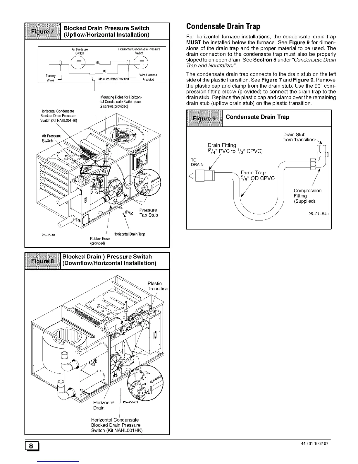
CondensateDrainTrap
For horizontal furnace installations, the condensate drain trap
MUST be installed below the furnace. See Figure 9 for dimen-
sions of the drain trap and the proper material to be used. The
drain connection to the condensate trap must also be properly
sloped to an open drain. See Section 5 under "Condensate Drain
Trap and Neutralizer".
The condensate drain trap connects to the drain stub on the left
side of the plastic transition. See Figure 7 and Figure 9. Remove
the plastic cap and clamp from the drain stub. Use the 90° com-
pression fitting elbow (provided) to connect the drain trap to the
drain stub. Replace the plastic cap and clamp over the remaining
drain stub (upflow drain stub) on the plastic transition.
Condensate Drain Trap
Drain Fitting
(3/4" PVC to 1/2" CPVC)
,/
DRAIN
Drain Trap
OD CPVC
Drain Stub
from Transition'_.&
S
Compression
Fitting
(Supplied)
25-21-84a
Plastic
Transition
Horizontal
Drain
Horizontal Condensate
Blocked Drain Pressure
Switch (Kit NAHLOO1HK)
[_ 440 01 100201
 Loading...