2. Installation
Poison carbon monoxide gas Hazard.
This furnace can NOT be common vented or
connected to any type B, BW or L vent or vent
connector, nor to any portion of a factory-built or
masonry chimney. If this furnace is replacing a
previously common-vented furnace, it may be
necessary to resize the existing vent line and
chimney to prevent oversizing problems for the
other remaining appliance(s). See Venting and
Combustion Air Check in Gas Vent Installation
section. This furnace MUST be vented to the
outside,
Failure to properly vent this furnace or other
appliances can result in death, personal injury
and/or property damage.
DualCertifiedFurnace
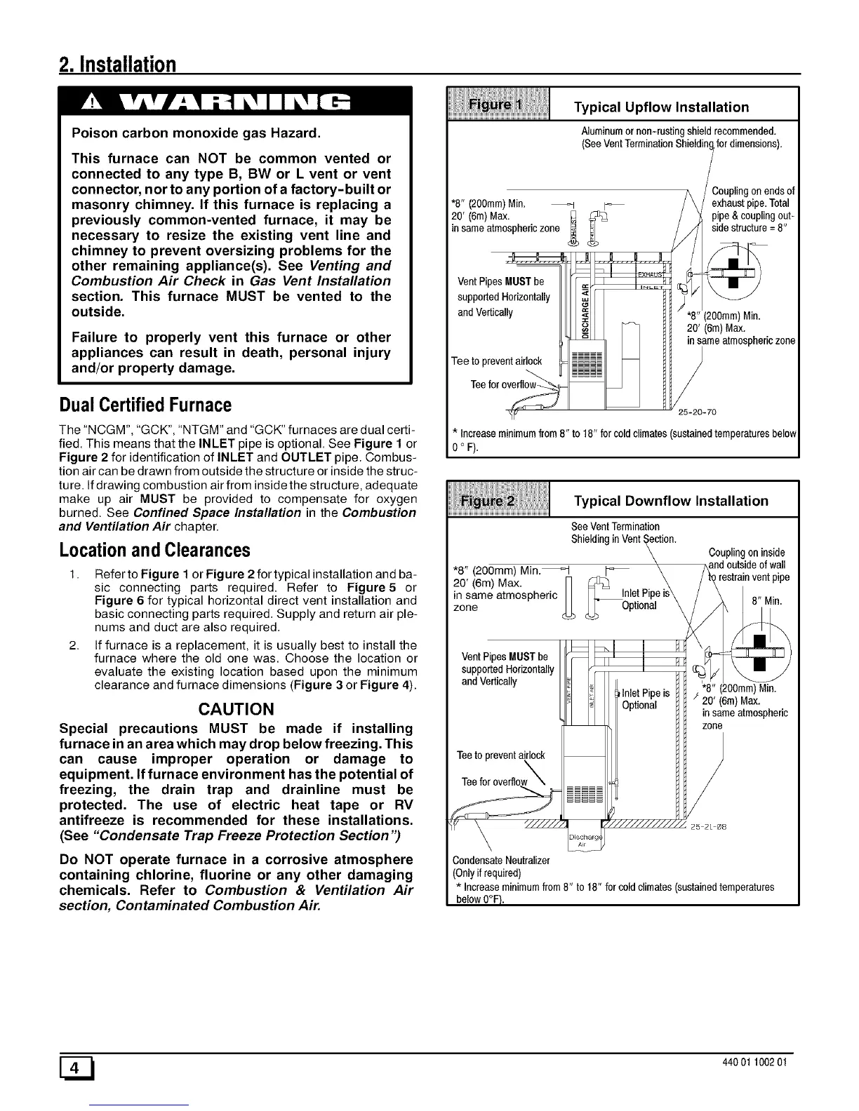
The"NCGM","GCK","NTGM"and "GCK"furnaces are dual certi-
fied. This means that the INLET pipe is optional. See Figure 1 or
Figure 2 for identification of INLET and OUTLET pipe. Combus-
tion aircan bedrawn from outside the structure or insidethe struc-
ture. Ifdrawing combustion airfrom insidethe structure, adequate
make up air MUST be provided to compensate for oxygen
burned. See Confined Space Installation in the Combustion
and Ventilation Air chapter.
Locationand Clearances
1. Refer to Figure 1 or Figure 2 for typical installation and ba-
sic connecting parts required. Refer to Figure5 or
Figure 6 for typical horizontal direct vent installation and
basic connecting parts required. Supply and return air ple-
nums and duct are also required.
2. If furnace is a replacement, it is usually best to install the
furnace where the old one was. Choose the location or
evaluate the existing location based upon the minimum
clearance and furnace dimensions (Figure 3 or Figure 4).
CAUTION
Special precautions MUST be made if installing
furnace in an area which may drop below freezing. This
can cause improper operation or damage to
equipment. If furnace environment has the potential of
freezing, the drain trap and drainline must be
protected. The use of electric heat tape or RV
antifreeze is recommended for these installations.
(See "Condensate Trap Freeze Protection Section ")
Do NOT operate furnace in a corrosive atmosphere
containing chlorine, fluorine or any other damaging
chemicals. Refer to Combustion & Ventilation Air
section, Contaminated Combustion Air.
*8" (200ram)Min.
20' (6m) Max.
in sameatmosphericzone
Typical Upflow Installation
Aluminumor non-rustingshieldrecommended.
(SeeVentTerminationShieldin fordimensions).
;ouplingon_nds of
exhaustpipe.Total
pipe&couplingout-
sidestructure=8"
'8" (200ram)Min.
20' (6m)Max.
insameatmosphericzone
25-20-70
* Increaseminimumfrom8" to 18" forcoldclimates(sustainedtemperaturesbelow
0 ° F).
Typical Downflow Installation
See VentTermination
Shielding inVent _ction.
\
*8" (200mm) Min._ _
20' (6m)Max. _> ___ InletPip
in same atmospheric _ Optional\
Zoiqe
supportedHorizontally
and Vertically
is
Teeto preventairlock
\
CondensateNeutralizer
(Onlyifrequired)
* Increaseminimumfrom8"to18"forcoldclimates(sustainedtemperatures
belowO°F}.
Couplingon inside
_re d outsideofwall
strainventpipe
"8"(200mm)Min.
/ 20' (6m)Max.
insameatmospheric
zone
[_ 440 01 100201
 Loading...