iiiiiiiiiiiiiiiiiiiiiiiiiiiiiiiiiiiiiiiiiiiiiiiiiiiiiiiiiiiiiiiiiiiiiiiiiiiiiiiiiiiiiiiiiiiiiiiiiiiiiiiiiiiiiiiiiiiiiiiiiiii
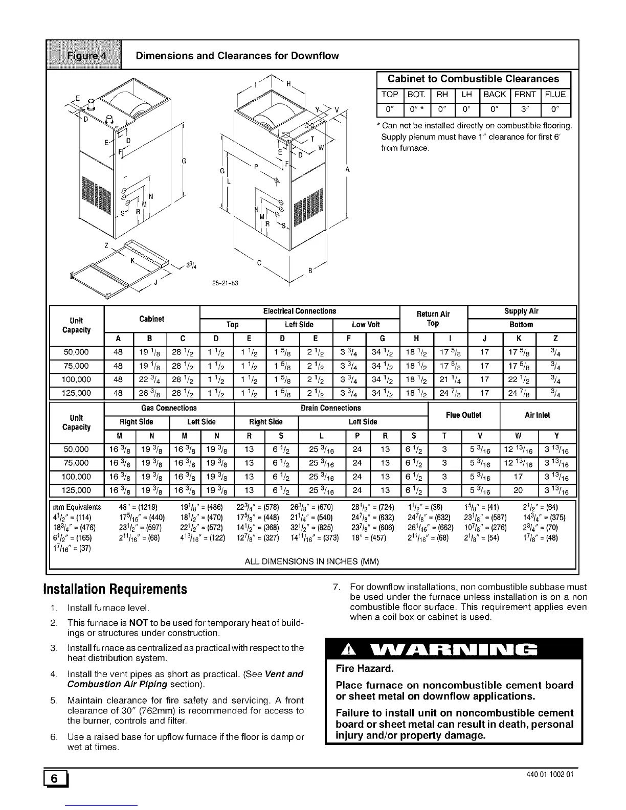
Dimensions and Clearances for Downflow
_ 33/4
¥ v
c B/
25-21-83 _"/
Cabinet to Combustible Clearances
TOP BOT. RH LH BACK FRNT FLUE
0" 0"* 0" 0" 0" 3" O"
* Can not be installed directly on combustible flooring.
Supp _'plenum must have 1" clearance for first 6'
from furnace.
Unit
Capacity
50,000
75,000
100,000
125,000
Unit
Capacity
50,000
75,000
100,000
125,000
Cabinet
A B C
48 191/8 28112
48 191/8 28112
48 223/4 28112
48 263/8 28112
Gas Connections
ElectricalConnections
Top Left Side LowVolt
D E D E F G
11/2 11/2 1 5/8 2 1/2 3 3/4 341/2
1 1/2 1 1/2 1 5/8 2 1/2 3 3/4 34 1/2
1 1/2 1 1/2 1 5/8 2 1/2 3 3/4 34 1/2
1 1/2 1 1/2 1 5/8 2 1/2 3 3/4 34 1/2
Right Side Left Side
M N M N
163/8 193/8 163/8 t93/8
163/8 193/8 163/8 t93/8
163/8 193/8 163/8 t93/8
163/8 193/8 163/8 t93/8
DrainConnections
ReturnAir
Top
H I J
181/2 175/8 17
181/2 175/8 17
181/2 21 1/4 17
181/2 247/8 17
FlueOutlet
SupplyAir
Bottom
K Z
t75_ 3_
t75_ 3_
2216 3_
247_ 3_
Air Inlet
RightSide LeftSide
R S L P R S
13 61& 25 _18 24 13 61&
13 61& 25 _18 24 13 61&
13 61_ 25 _16 24 13 61_
13 61_ 25 _16 24 13 61_
T
3
3
3
3
v
5 3/16
5 3/16
5 3/16
5 3/16
W
1213/16
1213/16
17
20
Y
3 13/16
3 13/16
3 13/16
3 13/16
ram Equivalents 48" = (1219) 191/8" = (486) 223/4" = (578) 263/8" = (670) 281/2" = (724) 11/2" = (38) 15/8" = (41) 21/2" = (64)
41/2" = (114) t75/16" = (440) 181/2" = (470) 175/8" = (448) 211/4" = (540) 247/8" = (632) 247t8" = (632) 23118" = (587) t43/4 " = (375)
t83/4" = (476) 231/2" = (597) 221/2" = (572) 141/2" = (368) 321/2', = (825) 237/8" = (606) 261/16" = (662) 107/8" = (276) 23/4" = (70)
61/2" = (165) 211/16" = (68) 413/16" = (122) 127/8" = (327) 1411116"= (373) 18" = (457) 211t16" = (68) 21/8" = (54) 17/8" = (48)
t7/16" = (37)
ALL DIMENSIONS IN INCHES (MM)
InstallationRequirements
1. Install furnace level.
2. This furnace is NOT to be used for temporary heat of build-
ings or structures under construction.
3. Install furnace as centralized as practical with respect to the
heat distribution system.
4. Install the vent pipes as short as practical. (See Vent and
Combustion Air Piping section).
5. Maintain clearance for fire safety and servicing. A front
clearance of 30" (762mm) is recommended for access to
the burner, controls and filter.
6. Use a raised base for upflow furnace if the floor is damp or
wet at times.
7.
For downflow installations, non combustible subbase must
be used under the furnace unless installation is on a non
combustible floor surface. This requirement applies even
when a coil box or cabinet is used.
Fire Hazard.
Place furnace on noncombustible cement board
or sheet metal on downflow applications.
Failure to install unit on noncombustible cement
board or sheet metal can result in death, personal
injury and/or property damage.
[_ 44001100201
 Loading...