16
icos - Installation & Servicing
INSTALLATION
195mm
195mm
Rear flue length X
Side flue length L
Jacking screw
160 mm
Ecl 1177
160 + S = 193mm
13
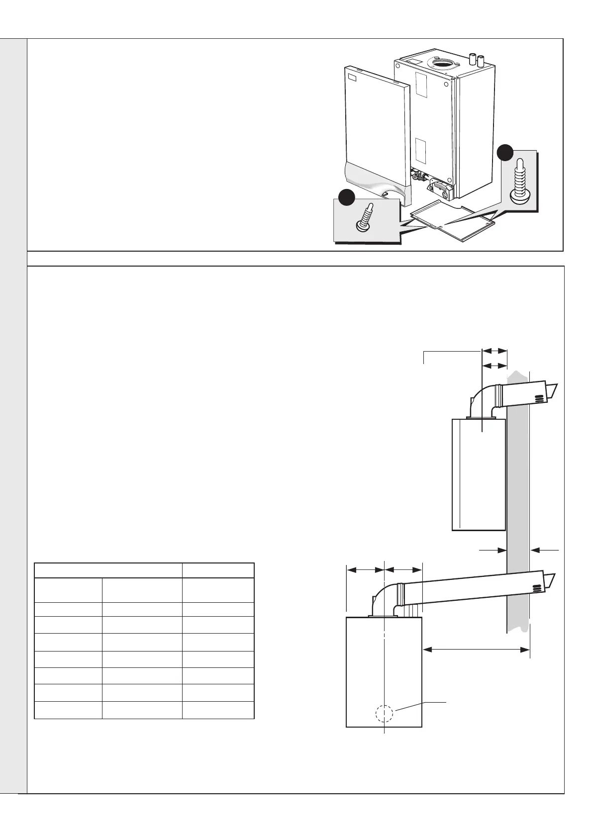
FRONT AND BOTTOM PANEL REMOVAL
IMPORTANT. The boiler MUST be installed in a vertical position
Dimension X - Wall thickness.
Dimension L - Wall thickness plus boiler spacing.
Dimension S - Stand-off frame depth = 33mm.
1. To remove the front panel remove the 2 screws from the
bottom panel.
2. Lift the panel up and off the top pegs.
3. To remove the bottom panel remove the 2 screws.
4. Pull the RH side of the panel down. Slide it to the right
and withdraw.
14
DETERMINING THE FLUE LENGTH AND FLUE PACKS REQUIRED
FLUE KITS
Pack B - supplied as standard
Finishing Kit - supplied as standard
Pack D - optional extension kit for side flue or rear flue outlet.
Refer to 'Flue Extension Ducts'
Note. MAXIMUM FLUE LENGTHS:
HORIZONTAL FLUE - 6M
ROOF FLUE KIT - 8M
POWERED VERTICAL FLUE KIT - 14M TOTAL
60/60 TWIN FLUE KIT - 20M TOTAL AIR PLUS FLUE DUCT
80/80 TWIN FLUE KIT - 46M TOTAL AIR PLUS FLUE DUCT
90
O
ELBOW KIT 60/100 (EQUIVALENT FLUE LENGTH RESISTANCE = 1M)
45
O
ELBOW KIT 60/100 (EQUIVALENT FLUE LENGTH RESISTANCE = 0.6M)
Notes.
1. The flue duct MUST be inclined at 1.5 degrees to the horizontal to allow condensate to drain back into the boiler and out
through the condensate drain.
2. If the boiler is to be installed with downward piping routed behind the boiler then the optional stand-off kit should be used.
Care must be taken when cutting the ducts and marking the wall to suit this condition.
nm 7802
3
1
Total Flue length dimension Flue
Rear flue Side flue Extra packs
dim. X+160 dim. L+195 required
Up to 650 mm Up to 650 mm none
Up to 1600 mm Up to 1600 mm Pack D - 1 off
Up to 2550 mm Up to 2550 mm Pack D - 2 off
Up to 3500 mm Up to 3500 mm Pack D - 3 off
Up to 4450 mm Up to 4450 mm Pack D - 4 off
Up to 5400 mm Up to 5400 mm Pack D - 5 off
Up to 6000 mm Up to 6000 mm Pack D - 6 off
INSTALLATION
200212-10.pmd 9/5/2005, 8:58 AM16
 Loading...