Do you have a question about the Ideal Boilers LOGIC MAX HEAT H 24 and is the answer not in the manual?
Instructions for fitting the flue through walls and terminals.
Guidance on safe and appropriate flue terminal placement.
Detailed wiring instructions and precautions for installers.
Procedures for initial checks and testing of the installed boiler.
Step-by-step guide for starting the boiler for the first time.
Detailed instructions for replacing the boiler fan.
How to replace the burner injector.
Detailed instructions for replacing the boiler burner.
Steps for replacing thermistors.
How to replace the ignition electrode.
Procedures for replacing the flame detection electrode.
Steps for replacing the spark generator.
How to replace the gas control valve.
Detailed instructions for replacing the condensate trap.
Steps for replacing the boiler's printed circuit board.
How to replace the water flow switch head.
Detailed instructions for replacing the heat engine assembly.
Troubleshooting steps for L1 fault code.
Troubleshooting steps for L2 fault code.
Troubleshooting steps for L6 fault code.
Troubleshooting steps for FA fault code.
Troubleshooting steps for Fd fault code.
Troubleshooting steps for flame loss faults.
Troubleshooting steps for fan-related faults.
Troubleshooting steps for thermistor faults.
Troubleshooting steps for return thermistor faults.
| Output Rating | 24 kW |
|---|---|
| Efficiency | 94% |
| ErP Space Heating Efficiency | A |
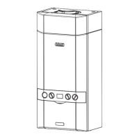
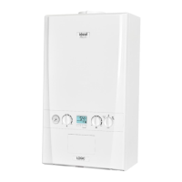
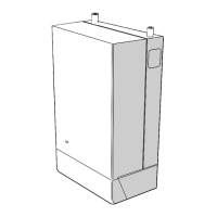
| Dimensions (HxWxD) | 700 x 395 x 278 mm |
| Fuel Type | Natural Gas |
| Warranty | 10 Years |
| Mounting | Wall-mounted |
| CH Output (kW) | 24 kW |
| Central Heating Flow Temperature Range | 30-80°C |