EasyManua.ls Logo

Ideal Boilers Logic System 15 - User Manual

Ideal Boilers Logic System 15
68 pages
Print Icon
To Next Page IconTo Next Page
Loading...
November 2009 UIN 204626 A03
INSTALLATION
AND SERVICING
LOGIC System
15, 18, 24, 30
For details of document amendments, refer to page 3
When replacing any part on this appliance, use only spare parts that you can be
assured conform to the safety and performance specification that we require.
Do not use reconditioned or copy parts that have not been clearly authorised by Ideal.
For the very latest copy of literature for specification and maintenance practices visit our
website www.idealboilers.com where you can download the relevant information in PDF format.
For users guide see reverse of book
January 2014
UIN 205552 A05
Question and Answer IconNeed help?

Do you have a question about the Ideal Boilers Logic System 15 and is the answer not in the manual?

Summary

Ideal Logic System Installation and Servicing

Notes for the Installer

Document Amendments

Lists changes implemented in this version of the manual.

General Data and Performance

Benchmark Commissioning Checklist Details

Introduction to the Logic System Boiler

Operation

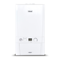
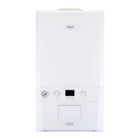
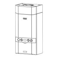
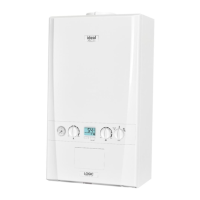
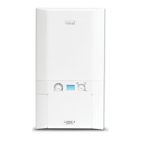
Explains how the boiler functions for heating and hot water.

Safe Handling

Provides essential safety precautions for moving and handling the boiler.

Safety and Regulatory Compliance

Location of Boiler

Specifies suitable and unsuitable locations for boiler installation.

Gas Supply Requirements

Flue Installation Guidelines

Provides instructions and regulations for fitting the flue system correctly.

System Requirements and Boiler Controls

Boiler Dimensions, Services, and Clearances

Central Heating System Requirements

System Balancing and Water Treatment

Boiler Assembly - Exploded View

Unpacking the Boiler and Components

Front Panel Removal and Installation Notes

Wall Mounting and Boiler Installation Steps

Determining Flue Length and Flue Packs

Flue Length Calculation and Pack Options

Cutting and Setting Flue Lengths

Installing the Flue and Turret Assembly

Fitting Optional Roof Flue Kits

Flue Terminal Positioning Guidelines

Assembling the Roof Flue Kit Components

Condensate Drain Installation and Prevention

Condensate Drain Connection Methods

Boiler Connections, Filling, and Electrical Setup

Internal Wiring Diagrams and Frost Protection

Mains Cable Replacement and External Controls

Boiler Wiring Diagram

Commissioning and Testing Procedures

Initial Lighting and Boiler Operation Checks

General Checks, System Reset, and Handover

Servicing Schedule and Procedures

Boiler Panel and Fan Assembly Servicing

Burner and Condensate Trap Servicing

Heat Exchanger Cleaning and Boiler Reassembly

Component Replacement - Fan

Burner Injector and Burner Replacement

Thermistor and Ignition Electrode Replacement

Flame Electrode and Spark Generator Replacement

Gas Valve and Condensate Trap Replacement

Main PCB Replacement Procedure

User Control PCB and Boiler Draining

Boiler Component Renewals - Gauge, Valve, Air Vent

Boiler Component Renewals - Pump, Sensor, Thermistor

Heat Engine Renewal Process

Expansion Vessel and Sealing Panel Servicing

Fault Finding Chart - Main Menu

Fault Finding - Overheat;No Flow & Ignition Lockout

Fault Finding - Flame Lockout, Water Pressure, Flame Loss

Fault Finding - Thermistor, Sensor, and BCC Issues

Fault Finding - No CH, No Display, No HW

Spare Parts Information

Benchmark Code of Practice for Installers

Benchmark Commissioning and Servicing Requirements

Gas Boiler System Commissioning Checklist

Service Record Log

Combustion Analysis for Condensing Boilers

Combustion Analysis Flowchart and Results

Manufacturer Information and Training

Ideal Logic System Users Guide

Consumer Helpline and Boiler Basics

Boiler Operation and Control Features

Condensate Drain and Emergency Procedures

Boiler User Troubleshooting Guide

Boiler Operation Modes Display Codes

Boiler Fault Codes and Actions

Ideal Boilers Logic System 15 Specifications

General IconGeneral
Output15 kW
MountingWall-mounted
ERP RatingA
Max Working Pressure3 bar
Central Heating Flow Temperature Range30-80°C
TypeSystem
Fuel TypeGas
Warranty2 years

Related product manuals