3
To force a timed delay on or off operation, set the mode
selector switch B in the TIMER position.
Set the time delay by pressing the button E or F and the
operation can be forced on or off by pressing the button G.
The time delay can be set within the following ranges:
1 to 23 hours with steps of 1 hour
1 to 27 days with steps of 1 day
The time delay setting is activated by moving the switch B to
the AUTO position.
The ON ---OFF display A flashes indicating that the current
state of operation has been forced.
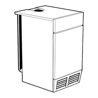
To delete the timed delay setting, set the mode selector
switch B in the TIMER position, press the button E or F until
the symbols shown in Fig. 5 appear in the display and then
set the mode selector switch B to the AUTO position
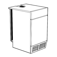
Setting example shown in Fig. 6:
forced ON state for 4 hours.
Fig. 6
Resetting
To completely reset the timer, press the reset button with a
pointed object (pencil).
CAUTION: pushing the reset button will completely erase the
settings as well as all the data, including the current time.
7 DAY DIGITAL PROGRAMMER
A
B
CDEFG
I
H
J
Display and control panel
A ON--- OFF display
B Mode selector switch
C Reset button
D Enter button
E Increase “+” setting button
F Decrease “--- ” setting button
G On--- off button
H Time display
I Day selection buttons
J Day display
Setting the current time and weekday
Note: with a new unit or when the reset button C has been
pressed and the selector switch B is to the position, the first
day indicator J on the left and the time display H are flashing.
Set the mode selector switch B to the position and press
the buttons E or F until the current time appears in the display
H.
Press the day selection button corresponding to the current
day, considering that button 1=Monday, button 2=Tuesday
and so on.
The clock starts by moving the switch B to the AUTO position.
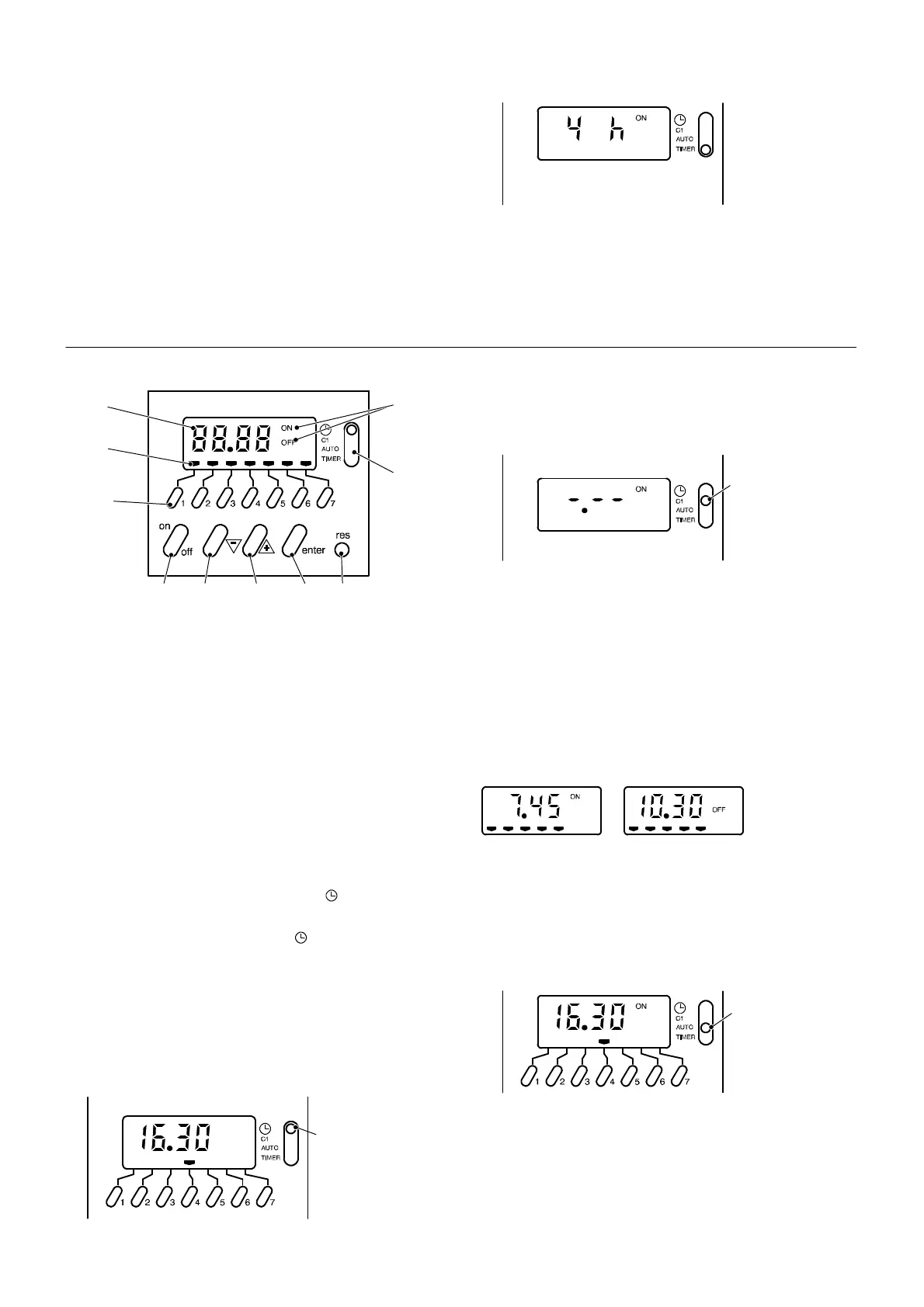
Setting example shown in Fig. 7:
Current time 16.30, day Thursday.
B
Fig. 7
Setting the switching time and day (or days)
20 memory locations are available, corresponding to 10
on--- off sequences.
Set the mode selector switch B to the C1 position. The
symbols shown in Fig. 8 appear in the display.
B
Fig. 8
Press the buttons E or F to set the desired ON time.
Press the buttons I to set the desired day or days of
operation.
Press the “enter” button D to confirm the setting and to
continue programming the OFF time.
Set the OFF time as explained above for the ON setting and
confirm by pressing the “enter” button D. Proceed in the
same way for other settings.
Setting example shown in Fig. 9:
A --- ON time 7.45, day Monday to Friday.
B --- OFF time 10.30, day Monday to Friday.
A B
Fig. 9
Activating the timed settings
Set the mode selector switch B to the AUTO position shown
in Fig. 10.
The current time and day appears in the display. The
ON ---OFF display A indicates the current state of operation
(according to the settings).
B
Fig. 10
Note: when the mode selector switch B is in the AUTO
position and the boiler is switched off at the fused spur
isolation switch, the display A indicates only the OFF state.
The other indications are blanked.
Reading the timed settings
Set the mode selector switch B to the C1 position. The
symbols shown in Fig. 8 appear in the display.