IDEAL INDUSTRIES, INC.
Sycamore, IL 60178, U.S.A.
800-435-0705
www.idealind.com
IS 0054-1
Made in China / Hecho en China / Fabriqué en Chine
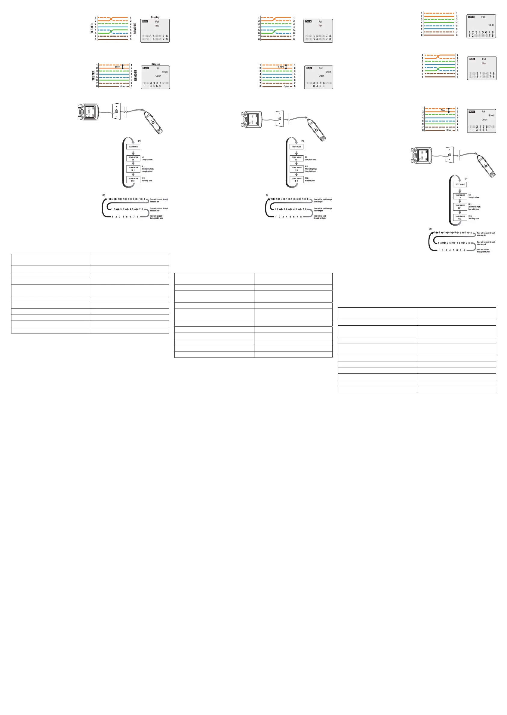
Reversed Wire Error (FAIL)
The pair on pins 1 and 2 is reversed and the
wires on pins 5 and 6 are crossed at one end
of the cable. Fail and Rev will appear on the
display and the pins with wiring errors will
flash. Pins 2 and 1 shown below pins 1 and 2
indicate a reversal on the Orange pair. Pins 6 and 5 shown
below 5 and 6 indicate a crossed connection.
Open and Short Wire Error (FAIL)
Pins 1 and 2 are shorted and the pair on pins 7
and 8 is open. Fail, Short and Open appear on
the display and the pins with wiring errors will
flash. Dash lines will appear below the shorted
pins and a blank space will appear below the
open pair.
Using the Tone Generator Function
NOTE: It is necessary to use a separate
(not included) analog amplifier probe
to hear the tone.
1. Connect the cable under test
to the RJ45 port on the tester.
2. Press and hold the MODE button. Release the MODE button as soon as
Tone appears on the LCD display.
3. To change tones, press the MODE button for approximately one
second. Refer to sequence chart (A) for description of tone
selection.
4. The pin that is sending the tone will be displayed at the bottom
of the LCD display. Repeatedly press the MODE button with
short presses to select the desired pins. Refer to
sequence chart (B)below for explanation of pin selection.
5. To turn off the tone generator, press and hold the MODE button.
Release the button as soon as OFF appears on the display.
NOTE: When tracing a cable run from the tone generator
to the end of the cable, applying the tone on a single
pin will allow the tone to be detected at a greater
distance from the cable. When trying to locate a cable
in an equipment room or patch panel, sending the tone
through all 8 pins or a single pair will limit the tone signal
from spreading to other nearby cables. The tone will be loudest when the probe tip is placed directly
on the wires the tone is being sent through at the end of the cable. when sending a tone through a
single pair, verification can be made by shorting the suspected pair. The tone will be very faint when
the pair the tone is being sent through is shorted.
General Specifications
Maintenance
• Keep the tester dry. If it gets wet, wipe it off. Do not use until the unit is completely dry.
• Clean with case with a dry cloth. Do not use chemicals, detergents or solvents.
• Use and store the tester in normal temperatures within the range noted above.
• Handle the tester with care. Dropping it can damage the electronic parts of the case.
• Remove the batter when the instrument will not be used for a longer period of time.
• There are no user serviceable parts inside the unit.
Battery Installation and Replacement
• Turn unit off.
• Remove the battery door with Phillips screwdriver.
• Open battery door.
• Install or replace the two AAA batteries.
• Replace battery door and screw.
Error de Cable Invertido (FALLO)
El par de los pines 1 y 2 se invierte y los hilos
de los pines 5 y 6 se cruzan en un extremo del
cable. Aparecerán Fail y Rev en la pantalla y los
pines con errores de cableado parpadearán. Los
pines 2 y 1 que se muestran debajo de los pines
1 y 2 indican una inversión en el par naranja. Los
pines 6 y 5 que se muestran debajo de 5 y 6 indican una conexión cruzada.
Error de Cable Abierto y Corto (FALLO)
Los pines 1 y 2 están en cortocircuito y el par
de los pines 7 y 8 está abierto. Aparecen Fail,
Short y Open en la pantalla y los pines con
errores de cableado parpadearán. Aparecerán
líneas discontinuas debajo de los pines en
cortocircuito y aparecerá un espacio en blanco
debajo del par abierto.
Uso de la Función de Generador de Tonos
NOTA: Es necesario utilizar una sonda
amplificadora analógica separada
(no incluida) para escuchar el tono.
1. Conecte el cable bajo prueba al
puerto RJ45 del probador.
2. Mantenga presionado el botón MODO.
Suelte el botón MODO tan pronto como aparezca
Tone en la pantalla LCD.
3. Para cambiar los tonos, presione el botón MODO durante
aproximadamente un segundo. Consulte la tabla de secuencia
(A) para obtener una descripción de la selección de tonos.
4. El pin que envía el tono se mostrará en la parte inferior de la
pantalla LCD. Presione repetidamente el botón MODO
con pulsaciones cortas para seleccionar los pines deseados.
Consulte la tabla de secuencia (B) para obtener una explicación
de la selección de pines.
5. Para apagar el generador de tonos, presione y
mantenga presionado el botón MODO. Suelte el
botón tan pronto como aparezca OFF en la pantalla.
NOTA: Al rastrear un tendido de cable desde el
generador de tonos hasta el final del cable, aplicar el
tono en un solo pin permitirá que el tono se detecte a una mayor distancia del cable. Al intentar
ubicar un cable en una sala de equipos o panel de conexión, enviar el tono a través de los 8 pines
o un solo par limitará la propagación de la señal del tono a otros cables cercanos. El tono será más
fuerte cuando la punta de la sonda se coloque directamente sobre los cables a través de los cuales
se envía el tono al final del cable. Al enviar un tono a través de un solo par, la verificación se puede
realizar poniendo en cortocircuito el par sospechoso. El tono será muy débil cuando el par por el
que se envía el tono esté en cortocircuito.
Especificaciones generales
Mantenimiento
• Mantenga el probador seco. Si se moja, límpielo. No lo use hasta que la unidad esté completamente
seca.
• Limpiar el estuche con un paño seco. No utilice productos químicos, detergentes ni disolventes.
• Utilice y almacene el probador a temperaturas normales dentro del rango indicado anteriormente.
• Maneje el probador con cuidado. Si se cae, se pueden dañar las partes electrónicas de la carcasa.
• Retire la batería cuando el instrumento no se vaya a utilizar durante un período de tiempo prolongado.
• No hay piezas que el usuario pueda reparar dentro de la unidad.
Instalación y reemplazo de baterías
• Retire la tapa de la batería con un destornillador Phillips.
• Abra la compuerta de la batería.
• Instale o reemplace las dos baterías AAA.
• Vuelva a colocar la tapa de la batería y el tornillo.
NOTE: It is necessary to use a separate amplifier probe in order to hear
the tone.
1. Connect the cable under test to the RJ45 port on the tester.
2. Press and hold the MODE button.Release the MODE button as soon
as Tone appears on the LCD display.
3. To change tones, press the MODE button for approximately one
second. Refer to sequence chart (A) for description of tone selection.
The pair on pins 1 and 2 is reversed and the wires on pins 5 and 6 are
crossed at one end of the cable. Fail and Rev will appear on the
display and the pins with wiring errors will flash. Pins 2 and 1 shown
below pins 1 and 2 indicate a reversal on the Orange pair. Pins 6 and
5 shown below 5 and 6 indicate a crossed connection.
Pins 1 and 2 are shorted and the pair on pins 7 and 8 is open. Fail,
Short and Open appear on the display and the pins with wiring errors
will flash. Dash lines will appear below the shorted pins and a blank
space will appear below the open pair.
Using the Tone Generator to Trace a Data Cable
T568B Data Cable With Reversed Pair and Crossed Connection
T568B Data Cable With a Shorted and Open Pair
4. The pin that is sending the tone will
be displayed at the bottom of the LCD
display.Repeatedly press the MODE
button with short presses to select the
desired pins. Refer to sequence chart
(B) below for explanation of pin
selection.
5. To turn off the tone generator,press
and hold the MODE button. Release
the button as soon as OFF appears on
the display.
MODE
Data Tone
1 2 3 4 5 6 7 8
Cable Types
Shielded or unshielded: CAT7; CAT 6A, CAT6,
CAT5e, CAT3 (8 conductor)
Maximum Cable Resistance 100 Ohms DC
Minimum Cable Length for Split Pair Detection 1.6 ft. (0.6m)
Maximum Cable Length 1000 ft. (305m)
Maximum Voltage Protection between any two
pins
60V DC; 55V AC
Dimensions 5.1*2.2*1.1 in. (128*55*28mm)
Weight 5 oz (144g)
Humidity 10% to 90%, non-condensing
Operating Temperature 32°F~122°F (0°C~50°C)
Storage Temperature -4°F~140°F (-20°C~60°C)
Battery 1.5V AAA x 2 (main unit)
Tipos de Cable Blindado o No Blindado:
CAT7; CAT 6A, CAT6, CAT5e, CAT3 (8
conductores)
Resistencia Máxima del Cable 100 ohmios CD
Longitud Mínima del Cable para la Detección de
Pares Divididos
1.6 pies (0.6 m)
Longitud Máxima del Cable 1000 pies (305 m)
Protección de Voltaje Máximo entre dos pines
cualesquiera
60 V CD; 55 V CA
Dimensiones 5.1*2.2*1.1 pulgadas (128*55*28 mm)
Peso Por Determinar 5 oz (144 g)
Humedad 10% al 90%, sin condensación
Temperatura de Funcionamiento 32°F~122°F (0°C~50°C)
Temperatura de Almacenamiento -4°F~140°F (-20°C~60°C)
Batería 1.5 V AAA x 2 (unidad principal)
Types de câbles
Blindés ou non blindés: CAT7; CAT 6A, CAT6,
CAT5e, CAT3 (8 conducteurs)
Résistance maximale du câble 100 Ohms CC
Longueur minimale du câble pour la détection de
paires divisées
1,6 pi. (0,6 m)
Longueur maximale du câble 1000 pi. (305 mètres)
Protection de tension maximale entre deux
broches quelconques
60 V CC; 55 V CA
Dimensions 5,1*2,2*1,1 po. (128 * 55 * 28 mm)
Pids 5 oz (144 g)
Humidité 10% à 90%, sans condensation
Température de fonctionnement 0 ° C ~ 50°C (32°F~122 ° F)
Température de stockage -20°C~60°C (-4°F~140°F)
Pile 1,5 V AAA x 2 (unité principale)
Erreur de paire divisée (FAIL)
Il y a une séparation entre les paires sur les
broches 3, 4 et 5, 6. FAIL (échec) et SPLIT
(division) s’affiche et les numéros de broche
avec la division clignotent pour indiquer quelles
paires sont divisées.
Erreur de fil inversé (FAIL) (Échec)
La paire sur les broches 1 et 2 est inversée et
les fils sur les broches 5 et 6 sont croisés à une
extrémité du câble. Fail et Rev seront affichés et
les broches avec des erreurs de câblage
clignoteront. Les broches 2 et 1 illustrées
ci-dessous les broches 1 et 2 indiquent une
inversion sur la paire orange Les broches 6 et
5 ci-dessous 5 et 6 indiquent une connexion croisée.
Erreur de fil ouvert et court-circuit (FAIL) (Échec)
Les broches 1 et 2 sont court-circuitées et la paire
sur les broches 7 et 8 est ouverte. Échec, Court-
circuit et Ouvert sont affichés et les broches avec
des erreurs de câblage clignotent. Des tirets
apparaîtront sous les broches court-circuitées et
un espace vide apparaîtra sous la paire ouverte.
Utilisation de la Fonction Générateur de Tonalité
REMARQUE : Il est nécessaire d’utiliser une
sonde d’amplificateur analogique séparée
(non incluse) pour entendre la tonalité.
1. Connectez le câble testé au port RJ45
du testeur.
2. Appuyez sur le bouton MODE et maintenez-le enfoncé.
Relâchez le bouton MODE dès que la tonalité s’affiche sur
l’écran LCD.
3. Pour changer de tonalité, appuyez sur le bouton MODE
pendant environ une seconde. Reportez-vous au diagramme
de séquence (A) pour la description de la sélection de tonalité.
4. Le code PIN qui envoie la tonalité sera affiché en bas de l’écran
LCD. Appuyez plusieurs fois sur le bouton de MODE avec de
brèves pressions pour sélectionner les broches souhaitées.
Reportez-vous au diagramme de séquence (B) pour une
explication de la sélection des broches.
5. Pour désactiver le générateur de tonalité, appuyez
sur le bouton MODE et maintenez-le enfoncé.
Relâchez le bouton dès que OFF apparaît à l’écran.
REMARQUE: Lors du traçage d’un câble allant du
générateur de tonalité à l’extrémité du câble, l’application de la tonalité sur une seule broche
permettra de détecter la tonalité à une plus grande distance du câble. Lorsque vous essayez de
localiser un câble dans une salle d’équipement ou un panneau de brassage, l’envoi de la tonalité via
les 8 broches ou une seule paire limitera la propagation du signal de tonalité aux autres câbles à
proximité. La tonalité sera plus forte lorsque la pointe de la sonde est placée directement sur les fils
à travers lesquels la tonalité est envoyée à l’extrémité du câble. lors de l’envoi d’une tonalité via une
seule paire, la vérification peut être effectuée en court-circuitant la paire soupçonnée. La tonalité sera
très faible lorsque la paire à travers laquelle la tonalité est envoyée est court-circuitée.
Caractéristiques Générales
Entretien
• Gardez le testeur au sec. S’il est mouillé, essuyez-le. Ne pas utiliser tant que l’appareil n’est pas
complètement sec.
• Nettoyer avec l’étui avec un chiffon sec. N’utilisez pas de produits chimiques, de détergents ou de
solvants.
• Utilisez et stockez le testeur à des températures normales comprises dans la plage indiquée
ci-dessus.
• Manipulez le testeur avec précaution. Le laisser tomber peut endommager les composants
électroniques du boîtier.
• Retirez la pile lorsque l’instrument ne sera pas utilisé pendant une période prolongée.
• Il n’y a pas de pièces réparables par l’utilisateur à l’intérieur de l’appareil.
Installation et remplacement de la pile
• Éteignez l’appareil.
• Retirez le couvercle de la pile avec un tournevis cruciforme.
• Ouvrez le couvercle de la pile.
• Installez ou remplacez les deux piles AAA.
• Remplacez le couvercle et la vis de la batterie.
Pass appears on the display indicating a properly wired cable. The pin
numbers on the top row and bottom row are the same indicating
proper continuity.
Note: The T568A wiring standard is the same as T568B, except that
T568A swaps the green and orange pairs. Either standard will test
the same electrically, as long as the same standard is used on both
ends of the cable.
There is a split between the pairs on pins 3, 4 and 5, 6. Fail and Split
appear on the display and the pin numbers with the split will flash
indicating which pairs are split.
1. Connect a known good patch cable to the wall port or patch panel of
the cable being tested.
2. Connect the other end of the patch cable to the RJ45 port on the
tester.
3. Detach the remote from the bottom of the tester.
4. Connect another known good patch cable to the RJ45 port on the
remote.
5. Connect the other end of the patch cable to the wall port or patch
panel at the other end of the cable being tested.
6. Momentarily press the MODE button.
7. Explain the test results using the wiring and display examples shown
below.
Wiring and Display Examples for Data Cable
T568B Data Cable Properly Wired
T568B Data Cable With Split Pairs
The pairs cross over (transmit to receive and receive to transmit). Pass
and X-over will appear on the display and the pin numbers on the
bottom row indicate the corresponding cross over to the pin numbers
on the top row.
T568B Cross Over Data Cable Properly Wired
À DISTANCE
TESTEUR
Affichage
À DISTANCE
TESTEUR
Affichage
NOTE: It is necessary to use a separate amplifier probe in order to hear
the tone.
1. Connect the cable under test to the RJ45 port on the tester.
2. Press and hold the MODE button.Release the MODE button as soon
as Tone appears on the LCD display.
3. To change tones, press the MODE button for approximately one
second. Refer to sequence chart (A) for description of tone selection.
The pair on pins 1 and 2 is reversed and the wires on pins 5 and 6 are
crossed at one end of the cable. Fail and Rev will appear on the
display and the pins with wiring errors will flash. Pins 2 and 1 shown
below pins 1 and 2 indicate a reversal on the Orange pair. Pins 6 and
5 shown below 5 and 6 indicate a crossed connection.
Pins 1 and 2 are shorted and the pair on pins 7 and 8 is open. Fail,
Short and Open appear on the display and the pins with wiring errors
will flash. Dash lines will appear below the shorted pins and a blank
space will appear below the open pair.
Using the Tone Generator to Trace a Data Cable
T568B Data Cable With Reversed Pair and Crossed Connection
T568B Data Cable With a Shorted and Open Pair
4. The pin that is sending the tone will
be displayed at the bottom of the LCD
display.Repeatedly press the MODE
button with short presses to select the
desired pins. Refer to sequence chart
(B) below for explanation of pin
selection.
5. To turn off the tone generator,press
and hold the MODE button. Release
the button as soon as OFF appears on
the display.
MODE
Data Tone
1 2 3 4 5 6 7 8
À DISTANCE
TESTEUR
Affichage
PROBADOR
PROBADOR
REMOTAREMOTA
PANTALLA
PANTALLA
 Loading...