2
#61-164
#61-165
Intr
oduction
Utilizing patented technology, the SureTest
®
circuit analyzers
"look behind walls" to identify wiring problems that can lead to
personal shock hazards, electrical fires, or equipment performance issues. Personal shock
hazards stem from poor grounding, false grounds, and/or no ground fault protection.
Electrical fires are primarily caused from arc faults and high resistance points that lead to
glowing connections in the circuit wiring. And, equipment performance issues arise due to
insufficient voltage available under load, poor ground impedance, and high ground-to-neu-
tral voltage. In fact, it’s estimated that 80% of power quality performance issues are related
to the faulty wiring issues stated above.
Product Features
• True RMS
• Measures voltage drop under 12, 15 and 20-amp loads
• Measures voltage: Line, Ground-to-Neutral, Peak, Frequency
• Measures Hot, Neutral and Ground conductor impedances
• Identifies proper wiring in 3-wire receptacles
• Identifies false (bootleg) grounds
• Tests GFCIs for proper operation
• Tests AFCIs for proper operation (61-165)
• Checks for Shared Neutrals that lead to AFCI nuisance tripping (61-165)
• Verifies dedicated circuits (with 61-176 adapter)
• Includes 1-ft. extension cord and carrying case
General Operation
The SureTest
®
Circuit Analyzer takes only seconds to test each outlet and circuit under a full
load. This test tool checks for various wiring conditions including: correct wiring, polarity
reversal and no ground per UL-1436. A simple menu gives access to measurements of line
voltage, voltage drop under a full load condition, ground-neutral voltage and line impedances.
The ground fault circuit interrupter (GFCI) test is performed separately in accordance with UL-
1436 and disrupts the electrical supply if a functional GFCI is present.
The SureTest
®
w/AFCI, #61-165, also tests arc fault circuit interrupter (AFCI) devices to
ensure that AFCI breakers protecting the circuit have been installed correctly. This test dis-
rupts the electrical supply if a functional AFCI is present. This tool also checks for a shared
neutral condition that leads to AFCI nuisance tripping.
To maintain stated accuracies during repeated use, allow 20 seconds between insertions to
adequately dissipate any heat buildup during the load testing.
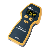
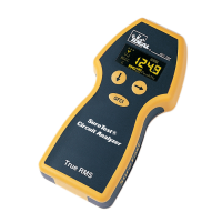
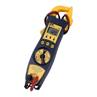
SureTest Circuit Analyzer
1. Menu Structure
2. Navigation Buttons
3. GFCI Test Button
4. AFCI Test Button
Menu Navigation
The microprocessor’s top priorities are to take live measurements and then analyze the data.
Hence, the microchip occasionally will not recognize the keypad buttons being rapidly
depressed, while it’s executing these routines. To avoid this issue, hold down the keypad
button each time until the menu changes.
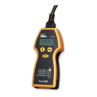
The measurements taken by the SureTest are broken into five main menus positioned down
the left side of the display: Wiring Configuration (•••), Voltage (V), Voltage Drop (V
D
),
ASCC, and Impedance (Z). To navigate to each of the main menus, use the down arrow
button ( ).
The Wiring Configuration (•••) screen indicates correct wiring, reverse polarity, hot/
ground reversal and no ground conditions by sequencing the three balls. The label on the
back of the product explains the wiring sequence indications.