Do you have a question about the IDEAL 61-768 and is the answer not in the manual?
Guidelines to avoid electric shock, personal injury, or death when using the meter.
Precautions for user protection, including PPE and safe measurement practices.
Lists common features of the 760 series clamp meters, like auto/manual ranging and display.
Explains the meaning of various symbols and safety categories found on the meter.
Details of the icons and elements shown on the meter's primary digital display.
Details of the icons and elements shown on the TightSight™ bottom display.
Describes the meter's indication for hazardous voltages, including LED and beep alerts.
Explains how to switch between automatic and manual ranging for measurements.
Details how to capture peak values and record min/max readings over time.
Describes freezing readings and zeroing the display for specific measurements.
Explains the automatic power down feature and how to operate the backlight.
Illustrates correct methods for measuring AC current, including single conductor and line splitter use.
Diagrams showing the correct setup for measuring AC and DC voltages.
Instructions and diagram for measuring resistance, emphasizing circuit de-energization.
Explains how to test for continuity and the resistance threshold for a beep.
Diagram showing the setup for measuring capacitance on the 61-766 model.
Diagrams illustrating frequency measurement in current and voltage modes for the 61-766 model.
Provides steps for battery replacement and guidance on cleaning the meter.
States that the unit has no user-serviceable parts and provides contact information.
Provides detailed technical specifications for the clamp meter, including displays and power.
Lists safety standards and certifications the meter complies with, including CAT ratings.
Distinguishes between averaging sensing and true RMS sensing for different models.
Specifies the accuracy of measurements, including conditions and tolerances.
Explains how temperature affects accuracy and lists overload protection limits.
Details the product warranty, coverage, limitations, and contact information.
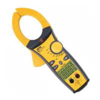
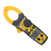
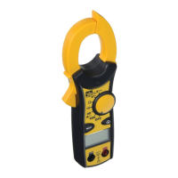
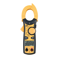
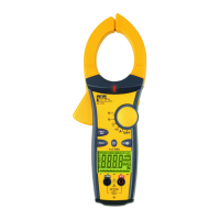
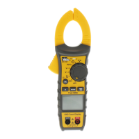
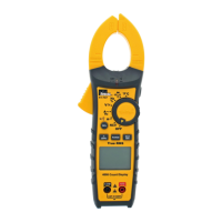
The IDEAL 600A Clamp Meters with TightSight™ Display are a series of instruction manuals for clamp meters, specifically models #61-764, #61-766, and #61-768. These devices are designed for measuring electrical parameters, with a focus on current, voltage, and resistance, and feature a unique bottom display for enhanced visibility in tight spaces.
The IDEAL 600A Clamp Meters are auto/manual ranging clamp meters. They are capable of measuring 600 AAC Current, AC/DC Voltage, and Resistance. An audible continuity feature is also included. For enhanced safety, the meters provide visual and audible indications when voltage is present, even if the meter is set to the wrong function.
The #61-764 model is an averaging sensing, RMS calibrated meter. The #61-766 model is a true RMS sensing meter that also measures capacitance, frequency, and lower currents with a 40 AAC range, making it suitable for troubleshooting motors and adjustable speed drives. The #61-768 model is also a true RMS sensing meter and measures DC current.
The clamp meters are equipped with several features to facilitate ease of use and accuracy.
Tapered Jaws with Hook Tip: The jaws are designed to be tapered, allowing access into tight spaces. A hook tip further aids in separating wires for individual measurements.
TightSight™ Bottom Display: A key feature of these meters is the TightSight™ bottom display. This secondary display is particularly useful for viewing current measurements in tight locations where the main display might be obscured. While the TightSight™ display primarily shows numerical values for AC/DC amps, the main display is used for viewing units of measure and other functions.
Main Display (LCD): The main display is a 4000-count LCD that shows large numbers and symbols. It includes icons for AC/DC measurement, polarity, range, auto power off (APO), data hold, max/min, peak max/min, audible continuity, volts, amps, farads, ohms, hertz, units of measure, an analog bar graph, and a low battery indicator.
High Voltage Warning (HI-V): For safety, the meter lights a red LED and beeps when 30V AC/DC voltage is present, regardless of the selected function. This ensures the user is alerted to dangerous voltage.
Auto/Manual Ranging Mode: The meter defaults to autoranging upon power-on, automatically selecting the best range for measurement. Users can switch to manual range mode by pressing the Range button, which locks in a specific range for repeated measurements. An "O" icon appears on the display when manual range is active. Holding the Range button for more than 1 second or cycling the power returns the meter to autoranging.
Peak Max/Min Feature: This feature captures peak voltage in VAC and peak current in AAC functions, with a 1 ms capture time for both P+ and P-. Users press the "PEAK" button to activate and toggle between P+ and P- readings. Holding the "PEAK" button for >2 seconds exits the feature. For more accurate peak measurements, the meter can be self-calibrated by holding the "PEAK" button for >2 seconds until "CAL" appears.
Max/Min Feature: The Max/Min feature records the maximum and minimum values measured over time. Pressing the Max/Min button activates this feature and allows toggling between Max, Min, and "MAXMIN" (which displays real-time readings while still capturing max/min values). Holding the Max/Min button for >2 seconds exits the mode. To record values for more than 30 minutes, the Auto Power Off (APO) feature must be defeated.
Data Hold Feature: The Hold button on the side of the meter toggles the data hold mode, freezing the current measurement on the display, indicated by "HOLD" on the main display. Pressing it again unlocks the display for real-time readings.
Relative Mode (△) (61-768 model only): This mode is used to zero out the display for DC current measurements, subtracting a non-zero offset. Pressing the "△" button again causes the "△" icon to flash and displays the original offset number. Holding the "△" button for >2 seconds exits this mode.
Backlight: A green backlight illuminates both the main and TightSight™ displays. The backlight for the main display remains lit for approximately 4.5 minutes to conserve battery power. The TightSight™ display's backlight only activates when the meter is in the Amp function.
Measuring AC Current (Amps): The clamp meter is designed to measure current on a single conductor. Attempting to measure multiple conductors will result in incorrect readings as currents will cancel out. For measuring current in a cord with multiple conductors, a line splitter should be used.
Measuring Voltage: The meter can measure both AC and DC voltage. Test leads are connected to the V-Ω input terminal and the COM input terminal. For DC voltage, the polarity indicator on the display shows the direction.
Measuring Resistance (Ohms): To measure resistance, the circuit must be de-energized. Test leads are connected to the V-Ω and COM input terminals.
Verifying Continuity (•))): Similar to resistance measurement, the circuit must be de-energized for continuity testing. The meter will beep if the resistance is less than 35 Ω, confirming continuity.
Capacitance (61-766 model only): The #61-766 model can measure capacitance. Test leads are connected to the V-Ω and COM input terminals.
Frequency (61-766 model only): The #61-766 model can measure frequency in both current mode (through the clamp head) and voltage mode (using test leads).
Battery Replacement: To replace the 9V battery, ensure test leads are disconnected from the circuit and input jacks. Remove the two screws from the battery cap, replace the battery, and reassemble the cap, tightening the screws.
Cleaning: The meter's case can be cleaned with a damp cloth and mild detergent. Abrasives or solvents should not be used.
Protective Rubber Boot: The meter is encased in a protective rubber boot, which helps guard against damage. A replacement boot is available if needed.
Electronic Overload Protection: The meter features electronic overload protection on all ranges, enhancing its durability and safety.
Auto Power Off (APO): To conserve battery life, the meter automatically powers off after approximately 30 minutes of inactivity. Pressing any button wakes it up, displaying the last reading. This feature can be overridden by holding the Range button while turning the function switch from Off to any other position, which removes "APO" from the display. Turning the meter off and on again restores the APO default.
| Category | Measuring Instruments |
|---|---|
| Model | 61-768 |
| Brand | IDEAL |
| Type | Digital Multimeter |
| AC Voltage | 600V |
| DC Voltage | 600V |
| AC Current | 10A |
| DC Current | 10A |
| Resistance | 40 MΩ |
| Continuity | Yes |
| Diode Test | Yes |
| Voltage Range | 600V |
| Resistance Range | 40 MΩ |
| Safety Rating | CAT III 600V |
| Battery | 2 x AAA |
| Display | LCD |
| Current Range | 10A |