9
- Installation & Servicing
INSTALLATION
5
6
1
7
8
31
10
2
1
12
4
3
20
23
24
15
16
21
18
17
19
25
21
11
13
14
9
9
22
W45/60
im 5564
10
12A
52
8
4
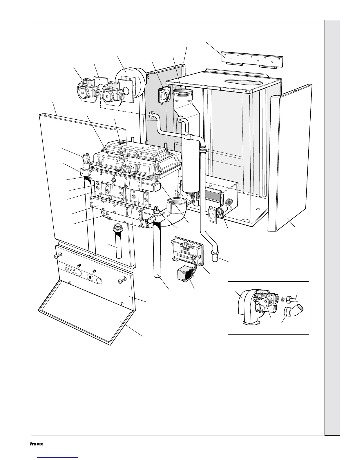
BOILER ASSEMBLY - Exploded View (W80 shown)
Legend
1. Jacket side panel
2. Jacket front panel assy.
3. Controls fascia
4. Controls door assy.
5. Wall mounting plate
6. Internal flue tube
7. Air pressure switch
8. Fan
9. Mounting plate manifold
10.Gas Valve
11. Upper gas pipe
12.Lower gas pipe
12A. Gas pipe
13.Sight glass complete
14.Ignition/detection electrode
15.Auto air vent
16.Manifold flow
17.AH-5 heat exchanger assy.
18.Inspection cover assy.
19.Condensate outlet pipe
20.Manifold return
21.Thermistor flow or return
22.Transformer
23.Control module
24.Pressure gauge
25.Water pressure switch
31.Gas manifold
52.45º elbow (W60/60P only)
INSTALLATION
 Loading...