50
SERVICING
isar - Installation and Servicing
2
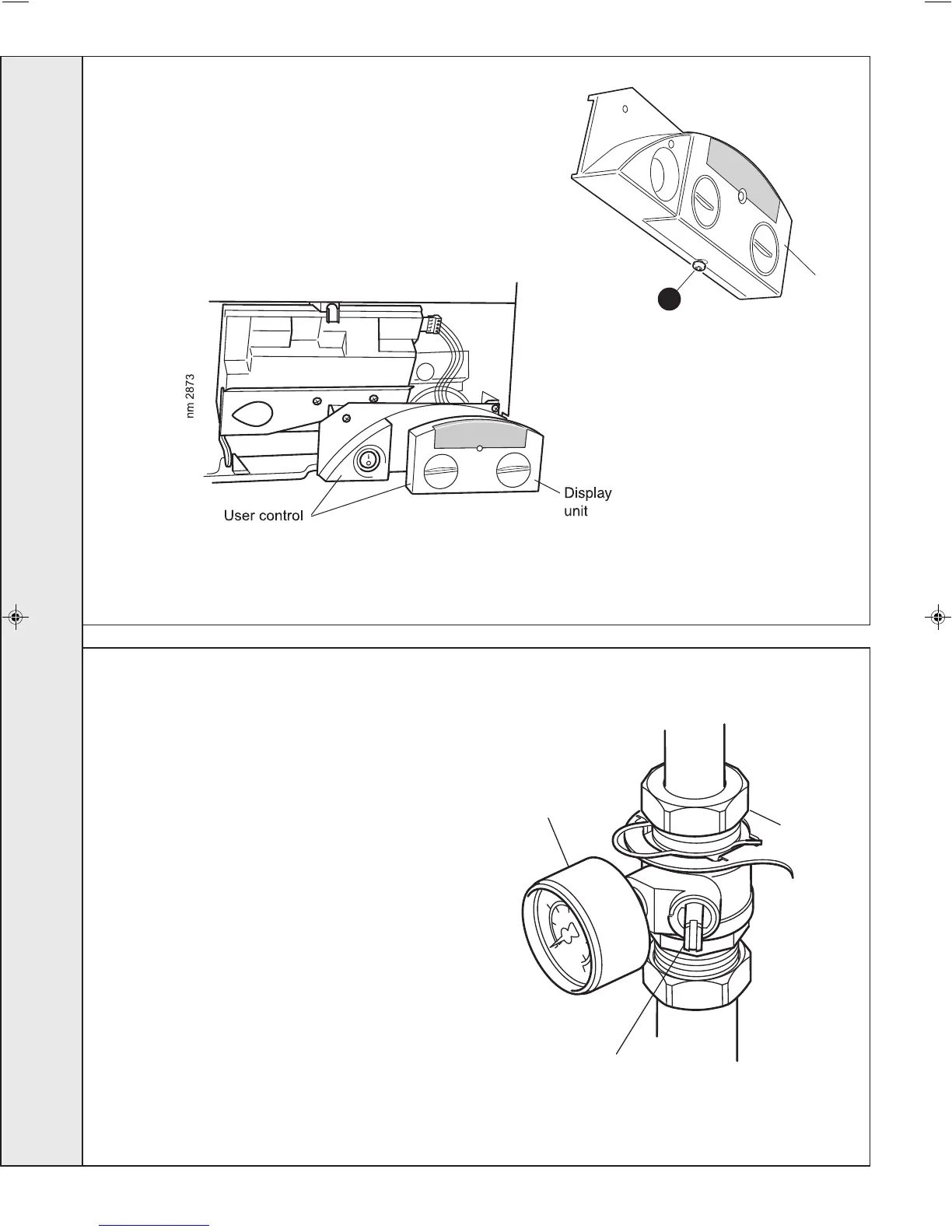
Display
unit
Ecl 2044
Note. Only the display unit is replaced.
1. Refer to Frame 57.
2. Loosen the screw on the underside of the user control.
3. Pull the display unit forward to remove.
4. Push the new display unit into position.
5. Reassemble in reverse order.
6. Check operation of the boiler. Refer to Frame 57.
73
USER CONTROL REPLACEMENT
74
PRESSURE GAUGE REPLACEMENT
1. Refer to Frame 57.
2. Drain the boiler. Refer to Frame 77.
3. Unscrew the pressure gauge and discard.
4. Fit the new pressure gauge, using a suitable jointing
compound.
5. Refill the boiler. Refer to Frame 36.
6. Check operation of the boiler. Refer to Frame 57.
2041
Pressure gauge
Flow isolation valve
(shown in the open position)
SERVICING
203319-3.pmd 27/03/2008, 08:1550

 Loading...