6: ALLOCATION NUMBERS
« FC4A MICROSMART USER’S MANUAL » 6-19
I/O Expansion for Slim Type CPU Modules
All slim type CPU modules can connect a maximum of seven expansion I/O modules including analog I/O modules.
The expandable I/O points and the maximum total I/O points vary with the type of CPU module as listed below.
Allocation Numbers (Slim Type CPU Modules)
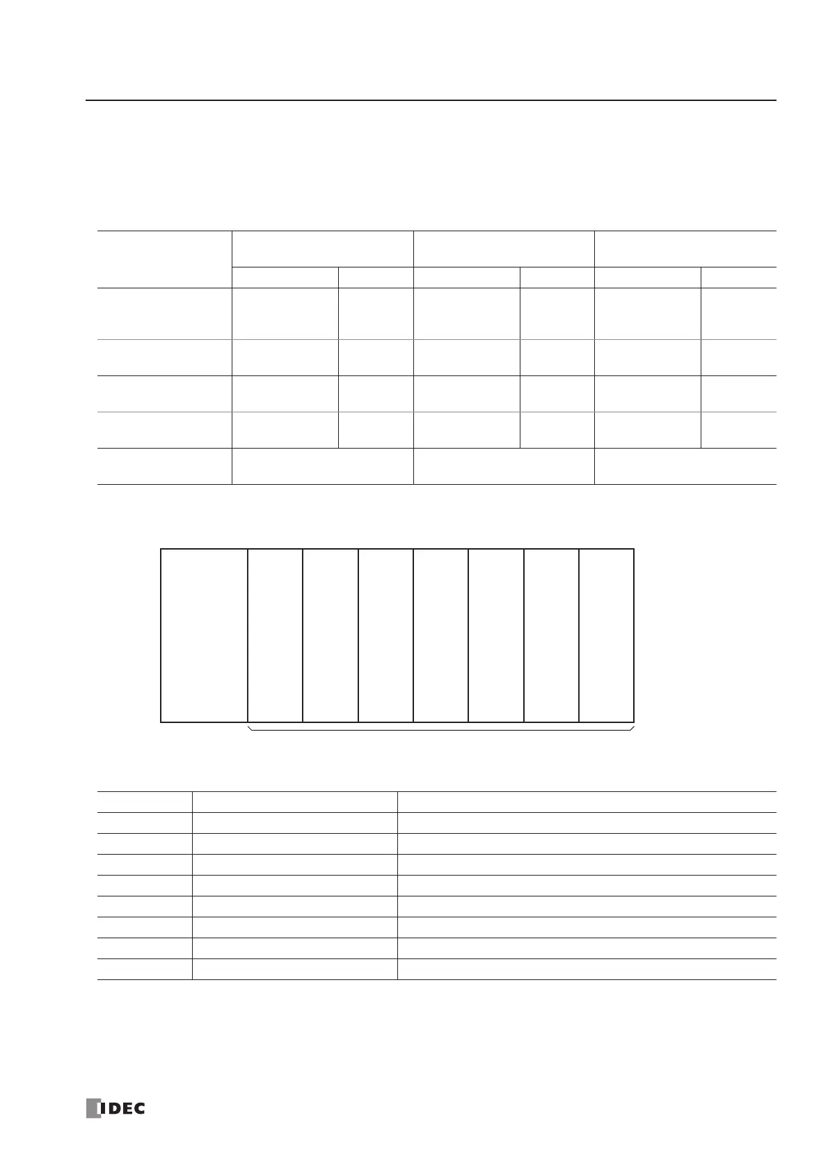
Example:
The system setup shown above will have I/O operand numbers allocated for each module as follows:
The I/O numbers of the CPU module start with I0 and Q0. The I/O numbers of the expansion I/O modules start with I30
and Q30. When an I/O module is mounted next to a 4/4-point mixed I/O module, note that the allocation numbers skip
four points as shown above.
Input and output modules may be grouped together for easy identification of I/O numbers. When the I/O modules are relo-
cated, the I/O numbers are renumbered automatically.
Operand
FC4A-D20K3
FC4A-D20S3
FC4A-D20RK1
FC4A-D20RS1
FC4A-D40K3
FC4A-D40S3
Allocation No. Points Allocation No. Points Allocation No. Points
Input (I)
I0 - I7
I10 - I13
12
I0 - I7
I10 - I13
12
I0 - I7
I10 - I17
I20 - I27
24
Expansion Input (I) I30 - I187
128
(140 total)
I30 - I307
224
(236 total)
I30 - I307
224
(248 total)
Output (Q) Q0 - Q7 8 Q0 - Q7 8
Q0 - Q7
Q10 - Q17
16
Expansion Output (Q) Q30 - Q187
128
(136 total)
Q30 - Q307
224
(232 total)
Q30 - Q307
224
(240 total)
Maximum Total
I/O Points
148 244 264
Slot No. Module I/O Operand Numbers
40-I/O Type CPU Module I0 to I7, I10 to I17, I20 to I27, Q0 to Q7, Q10 to Q27
1 32-pt Output Module Q30 to Q37, Q40 to Q47, Q50 to Q57, Q60 to Q67
2 16-pt Input Module I30 to I37, I40 to I47
3 16/8-pt Mixed I/O Module I50 to I57, I60 to I67, Q70 to Q77
4 8-pt Input Module I70 to I77
5 Analog I/O Module See page 24-8.
6 4/4-pt Mixed I/O Module I80 to I83, Q80 to Q83
7 32-pt Input Module I90 to I97, I100 to I107, I110 to I117, I120 to I127