17: USER COMMUNICATION INSTRUCTIONS
17-24 « FC4A MICROSMART USER’S MANUAL »
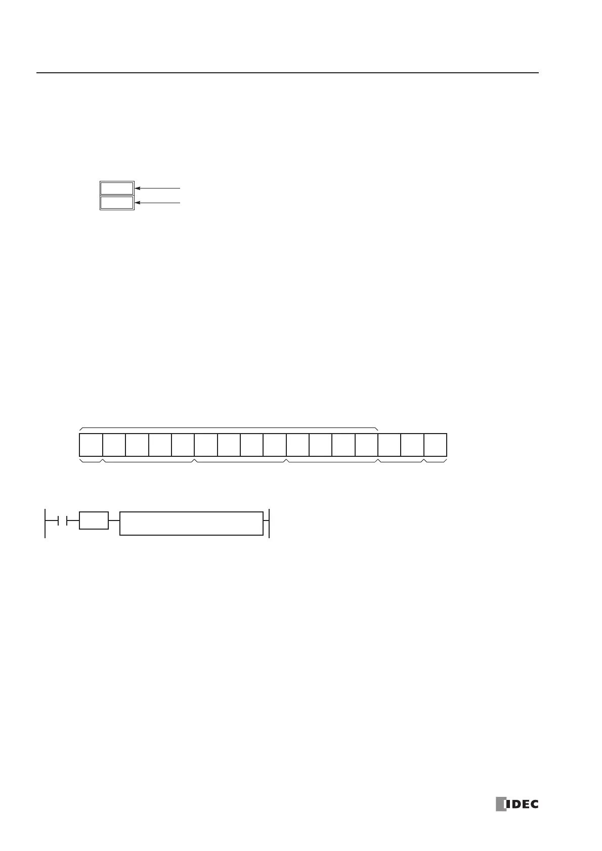
Receive Data Byte Count
The data register next to the operand designated for receive status stores the byte count of data received by the RXD
instruction. When a start delimiter, end delimiter, and BCC are included in the received data, the byte counts for these
codes are also included in the receive data byte count.
Example: Data register D200 is designated as an operand for receive status.
User Communication Receive Instruction Cancel Flag M8022/M8023
Special internal relays M8022 and M8023 are used to cancel all RXD1 and RXD2 instructions, respectively. While the
MicroSmart has completed receive format and is ready for receiving incoming data, turning on M8022 or M8023 cancels
all receive instructions for port 1 or port 2, respectively. This function is useful to cancel receive instructions only, without
stopping the MicroSmart.
To make the cancelled RXD instructions active, turn off the flag and turn on the input to the RXD instruction again.
Programming RXD Instruction Using WindLDR
The following example demonstrates how to program a RXD instruction including a start delimiter, skip, BCC, and end
delimiter using WindLDR. Converted data is stored to data registers D20 and D21. Internal relay M20 is used as destination
D1 for the receive completion output. Data register D200 is used as destination D2 for the receive status, and data register
D201 is used to store the receive data byte count.
Receive data example:
RXD sample program:
1. Start to program a RXD instruction. Move the cursor where you want to insert the RXD instruction, and type RXD.
You can also insert the RXD instruction by clicking the User Communication icon in the menu bar and clicking where
you want to insert the RXD instruction in the program edit area, then the Transmit dialog box appears. Click RXD to
change the dialog box to the Receive dialog box.
The Receive instruction dialog box appears.