20: PULSE INSTRUCTIONS
« FC4A MICROSMART USER’S MANUAL » 20-17
Destination Operand D1 (Status Relay)
Four internal relays starting with the operand designated by D1 indicate the status of the RAMP instruction. These oper-
ands are for read only.
D1+0 Pulse Output ON
The internal relay designated by operand D1+0 remains on while the RAMP instruction generates output pulses. When the
start input for the RAMP instruction is turned off or when the RAMP instruction has completed generating a predeter-
mined number of output pulses, the internal relay designated by operand D1+0 turns off.
D1+1 Pulse Output Complete
The internal relay designated by operand D1+1 turns on when the RAMP instruction has completed generating a predeter-
mined number of output pulses or when the RAMP instruction is stopped to generate output pulses. When the start input
for the RAMP instruction is turned on, the internal relay designated by operand D1+1 turns off.
D1+2 Pulse Output Status
The internal relay designated by operand D1+2 turns on while the output pulse frequency is increased or decreased, and
turns off when the output pulse frequency reaches the steady pulse frequency (S1+1). While the pulse output is off, the
internal relay designated by operand D1+2 remains off.
D1+3 Pulse Output Overflow
The internal relay designated by operand D1+3 turns on when the RAMP instruction has generated more than the prede-
termined number of output pulses (S1+6/7). When an overflow occurs, the current value (S1+8/9) stops at the preset value
(S1+6/7). When the start input for the RAMP instruction is turned on, the internal relay designated by operand D1+3 turns
off.
Special Data Register for Pulse Outputs
Upgraded CPU modules have two additional special data registers to store the current frequency of pulse outputs.
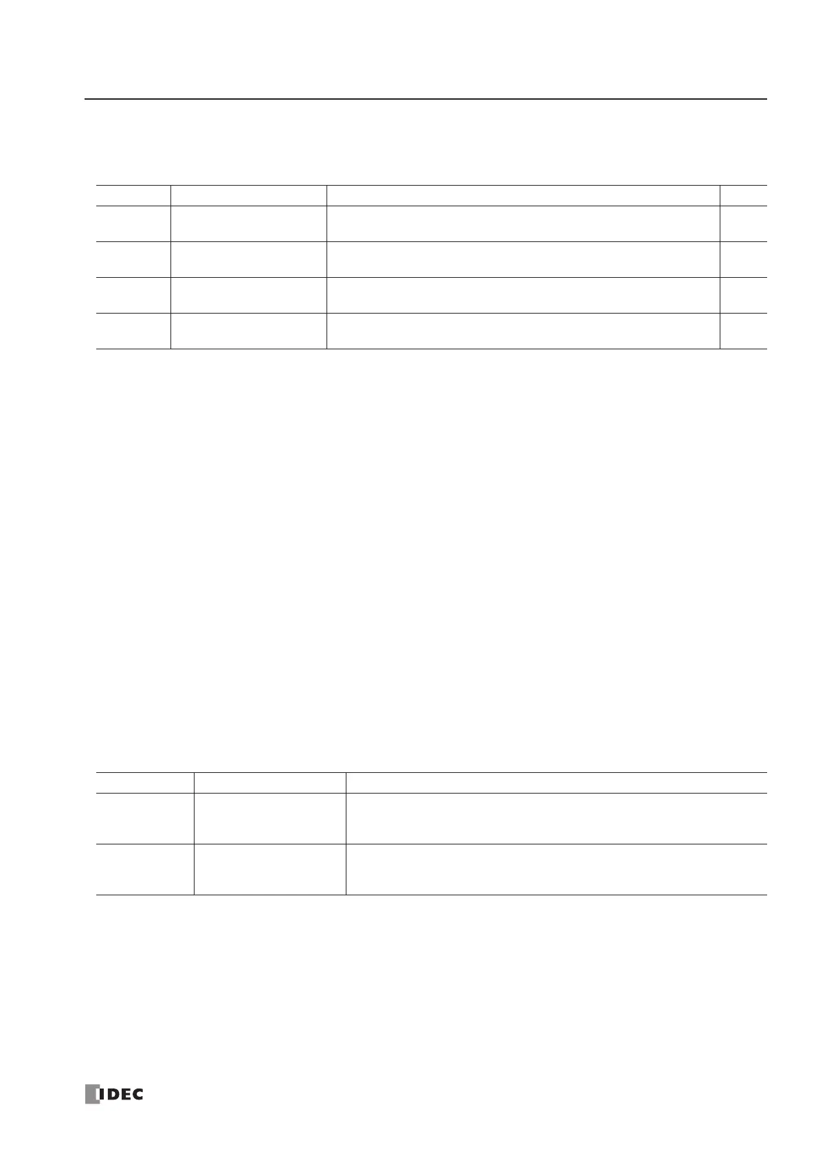
Operand Function Description R/W
D1+0 Pulse output ON
0: Pulse output OFF
1: Pulse output ON
R
D1+1 Pulse output complete
0: Pulse output not complete
1: Pulse output complete
R
D1+2 Pulse output status
0: Steady pulse output
1: Changing output pulse frequency
R
D1+3 Pulse output overflow
0: Overflow not occurred
1: Overflow occurred
R
Allocation No. Function Description
D8055
Current Pulse Frequency
of PULS1 or RAMP (Q0)
While the PULS1 or RAMP instruction is executed, D8055 stores the cur-
rent pulse frequency of output Q0.
The value is updated every scan.
D8056
Current Pulse Frequency
of PULS2 or RAMP (Q1)
While the PULS2 or RAMP (reversible control dual-pulse output) instruction
is executed, D8056 stores the current pulse frequency of output Q1.
The value is updated every scan.