21: PID INSTRUCTION
« FC4A MICROSMART USER’S MANUAL » 21-15
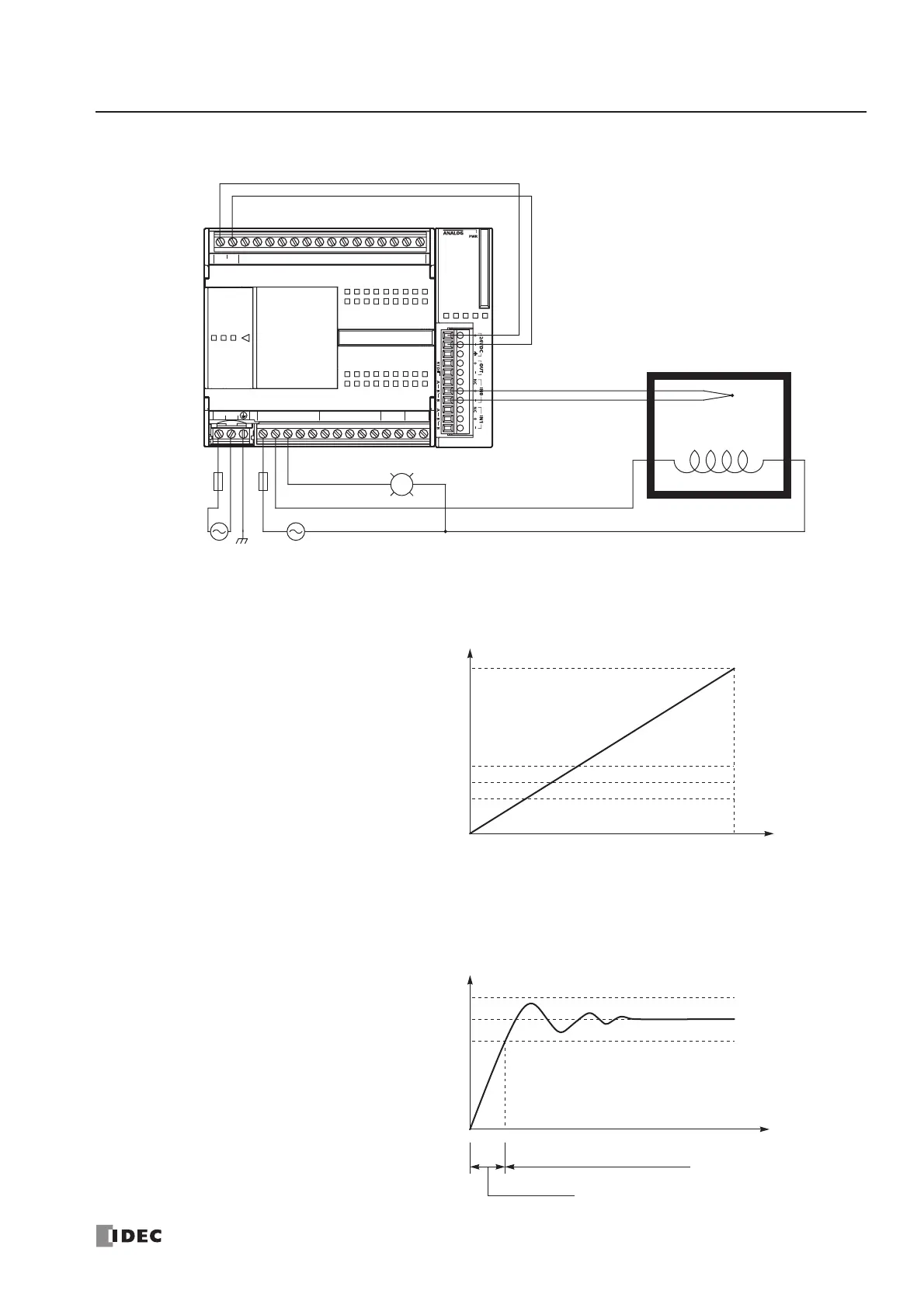
System Setup
Analog Input Data vs. Process Variable after Conversion
Temperature Control by Auto Tuning and PID Action
Type K
High Alarm Light
Output Q1
Heater
+24V 0V 10 11 12131415
DC OUT COM
DC IN 0 1 2 3 4 5 6 7
LN
100-240VAC Ry.OUT
COM0
Ry.OUT
COM1
Ry.OUT
COM3 11
Ry.OUT
COM2 100 1 2 3 4 5 6 7
Fuse
+
–
+
–
L
Output Q0
IN0
FC4A-C24R2 FC4A-L03AP1
Thermocouple
High Alarm Value (S1+14): 2500 (250°C)
4095
Linear Conversion Minimum Value (S1+6): 0 (0°C)
Linear Conversion Maximum Value (S1+5): 13000 (1300°C)
Set Point (S3): 2000 (200°C)
AT Set Point (S1+21): 1500 (150°C)
Analog Input Data D760
Process Variable after Conversion (S1+0)
Process Variable before Conversion (S4)
0
Process Variable after Conversion (S1+0)
Time
High Alarm Value (S1+14): 2500 (250°C)
Set Point (S3): 2000 (200°C)
AT Set Point (S1+21): 1500 (150°C)
Auto Tuning
PID Action