28: AS-INTERFACE MASTER COMMUNICATION
28-26 « FC4A MICROSMART USER’S MANUAL »
Slave Identification Information (Slave Profile)
Data registers D1780 through D1940 are assigned to the slave identification information, or the slave profile. The slave
profile includes configuration data and parameters to indicate the slave type and slave operation, respectively.
Configuration Data Image (CDI)
Data registers D1780 through D1843 are allocated to read the CDI of each slave. The CDI is the current slave configura-
tion data collected by the AS-Interface master module at power-up and stored in the AS-Interface master module.
The CDI is made up of four codes: the ID code, I/O code, ID2 code, and ID1 code. The CDI of slaves not connected to the
AS-Interface bus is FFFFh.
The ASI command Read CDI can be used to read the CDI data to data registers D1780 through D1843. Execute the ASI
command Read CDI before using the CDI data for program execution.
Permanent Configuration Data (PCD)
Data registers D1844 through D1907 are allocated to read and write the PCD of each slave. Like the CDI, the PCD is made
up of four codes: the ID code, I/O code, ID2 code, and ID1 code.
When auto configuration is executed, the CDI is copied to the PCD and stored in the EEPROM of the AS-Interface master
module. When you execute manual configuration, you can set the PCD using the Configure Slave dialog box on WindLDR.
Set the PCD of each slave to the same value as its CDI. If the PCD is different from the CDI for a slave, then that slave
does not function correctly. Set FFFFh to the PCD of vacant slave numbers.
The ASI command Read PCD can be used to read the PCD data to data registers D1844 through D1907. Execute the ASI
command Read PCD before using the PCD data for program execution.
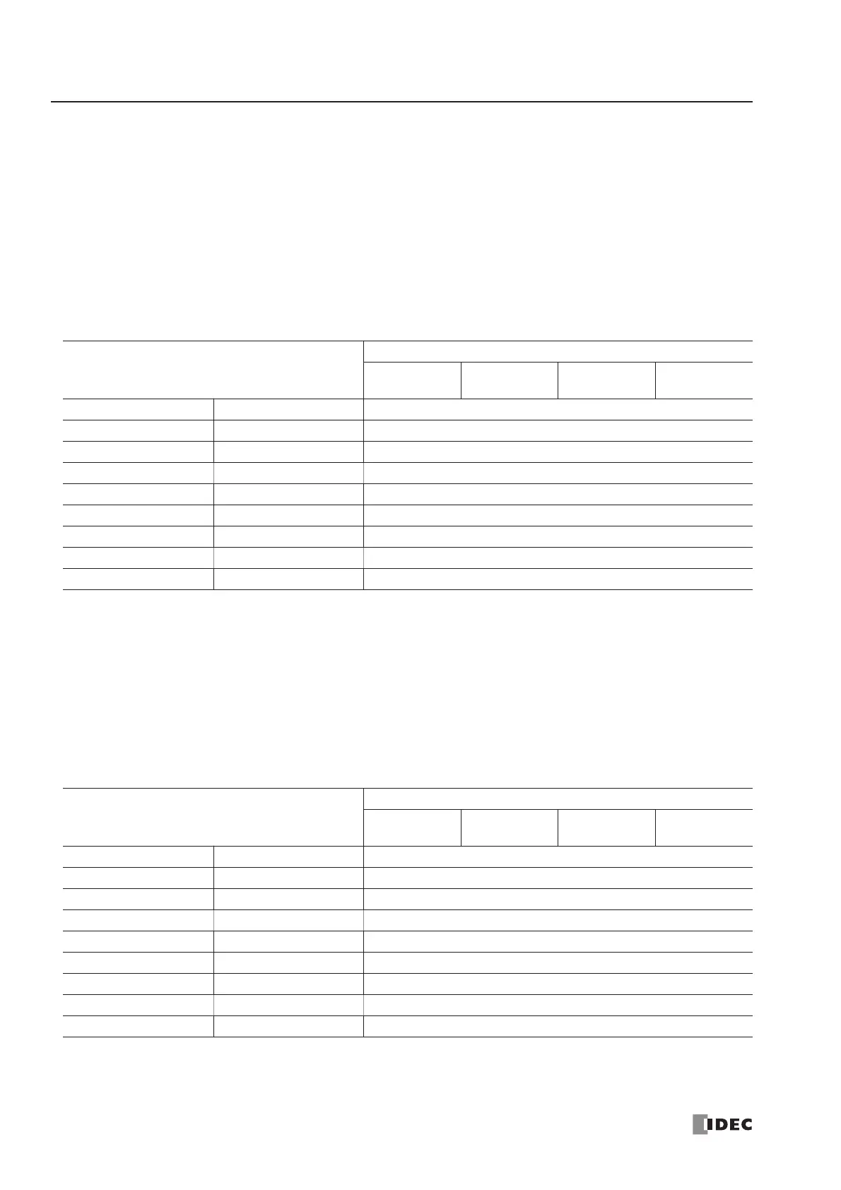
CDI
Data Format
Bits 15 to 12
ID Code
Bits 11 to 8
I/O Code
Bits 7 to 4
ID2 Code
Bits 3 to 0
ID1 Code
D1780 Bytes 0 and 1 Slave 0
D1781 Bytes 2 and 3 Slave 1(A)
D1782 Bytes 4 and 5 Slave 2(A)
D(1780+N) | Slave N(A)
D1811 Bytes 62 and 63 Slave 31(A)
D1812 Bytes 64 and 65 (unused)
D1813 Bytes 66 and 67 Slave 1B
D(1812+N) | Slave NB
D1843 Bytes 126 and 127 Slave 31B
PCD
Data Format
Bits 15 to 12
ID Code
Bits 11 to 8
I/O Code
Bits 7 to 4
ID2 Code
Bits 3 to 0
ID1 Code
D1844 Bytes 0 and 1 Slave 0
D1845 Bytes 2 and 3 Slave 1(A)
D1846 Bytes 4 and 5 Slave 2(A)
D(1844+N) | Slave N(A)
D1875 Bytes 62 and 63 Slave 31(A)
D1876 Bytes 64 and 65 (unused)
D1877 Bytes 66 and 67 Slave 1B
D(1876+N) | Slave NB
D1907 Bytes 126 and 127 Slave 31B