30
HR6S Safety Relay Module
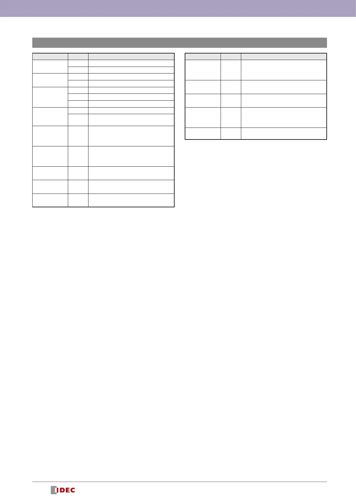
LED Display (Example for HR6S-AT)
LED State Explanation
POWER
Power supply on
No power supply
Snn
Safety-related input activated
Safety-related input deactivated
START
Valid start condition
No valid start condition
Waiting for valid start condition
STATEn (*3)
Normally open safety-related outputs activated
Normally open safety-related outputs
deactivated
ERROR
Snn (*1)
Snn (*1)
Synchronization time alert
Other LEDs retain normal behavior
ERROR
Snn (*2)
Snn (*2)
Interlock alert
Other LEDs retain normal behavior
ERROR
LEDs (*4)
General error detected
Module in dened safe state
ERROR
LEDs (*4)
Conguration error detected
ERROR
POWER
Power supply error detected
LED State Explanation
ERROR
Snn (*2)
Snn (*2)
Cross circuit detected at safety-related input
ERROR
START
Cross circuit detected at Start input
ERROR
STATEn (*3)
Error detected at safety-related output
ERROR
START
STATEn (*3)
Error detected at safety-related output of
expansion module
LEDs
All LEDs light up during power-up for
diagnostsics purposes.
: LED solid on
: LED off
: LED ashing
*1: Snn: n = number off LED of affected input, LEDs ashing alternatingly
*2: Snn: n = number off LED of affected input, LEDs ashing synchronously
*3: STATEn: n = 1 = Instantaneous
n = 2 = Delay
*4: LEDs: All LEDs except POWER
* For details, refer to the instruction sheet.