15
HR6S Safety Relay Module
HR6S-AT
Data Functional Safety
Dened safe state
Safety-related outputs are de-energized
Normally Open: open
Normally Closed: closed
Maximum Performance Level (PL), Category (as per
ISO 13849-1:2015)
Normally Open: PLe, Category 4
Normally Closed: PLc, Category 1
Maximum Safety Integrity Level (SIL)
(as per IEC 61508-1:2010)
Normally Open: 3
Normally Closed: 1
Safety Integrity Level Claim Limit (SILCL)
(as per IEC 62061:2005+AMD1:2012+
AMD2:2015)
Normally Open: 3
Normally Closed: 1
Type (as per IEC 61508-2) B
Hardware Fault Tolerance (HFT) (as per IEC 61508
and IEC 62061)
1
Stop Category for Emergency Stops
(as per ISO 13850 and IEC 60204-1)
0 or 1
Lifetime in years at an ambient temperature of 55 °C (131 °F)
20
Safe Failure Fraction (SFF)
(as per IEC 61508 and IEC 62061)
>99 %
Probability of Dangerous Failure per hour (PFH
D
) in 1/h
(as per IEC 61508 and ISO 13849-1)
0.94 × 10
-9
for Stop Category 0
0.95 × 10
-9
for Stop Category 1
Mean Time To Dangerous Failure (MTTF
D
) in years
(as per ISO 13849-1)
2,400 for Stop Category 0
2,300 for Stop Category 1 (*1)
Average Diagnostic Coverage (DC
avg
)
(as per ISO 13849-1)
≥99 %
Maximum number of cycles
over lifetime
DC-13
24V DC 1 A: 1200000 with Stop Category 0
24V DC 1 A: 1200000 with Stop Category 1
24V DC 3 A: 180000 with Stop Category 0
24V DC 3 A: 275000 with Stop Category 1
AC-1
250V AC 4 A: 180000 with Stop Category 0
250 VAC 4 A: 90000 with Stop Category 1
AC-15
250V AC 1 A: 70000 with Stop Category 0
250V AC 1 A: 90000 with Stop Category 1
250V AC 3 A: 39000 with Stop Category 0
250V AC 3 A: 60000 with Stop Category 1
*1) According to ISO 13849-1 Annex K
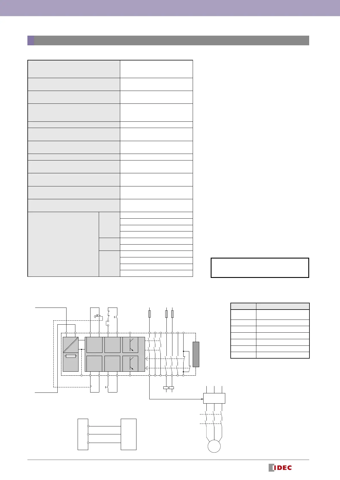
Wiring Example
F1 F2 F3
K5
K6
K5
K6
M
Motor
controller
PLC
Input1
Operation command
Input2
COM
(
0V
)
HR6S-AT1
※
Z1
Z2
B2
Common reference potential
(
0V
)
Semiconductor pulse output
(
DC24V
)
Semiconductor binary output
(
DC24V
)
K5 K6
ESC
S1
S2
75
76
L1 (
+
)
EXT
68
67
58
57
48
47
AC/DC
DC
DC+
Input
Input (*1)
Start
CH+ DC+ CH+
DC+ CH+
K2
K1
K4
K3
A1 A2 S11 S12 Y1 Y2
S21
S1
S3
S22 S31 S32B2*
N(
-
)
34
33
24
23
14
13
Input (*1)
DC- CH-
Z2
(*2) (*3)
Z1
(
*
)
Power
supply
For other specifications (common to all
models), see page 27.
Designation Explanation
EXT
Connector for optional
expansion module
S1 Emergency stop switch
S2 Start switch
S3 Off-delay cancel switch
K3, K4 Contactor
PLC Programmable controller
F1, F2, F3 Fuse
*1: Inputs that are not used for safety device
inputs can be used to cancel the delay
function for safety-related outputs.
*2:
Turns off while a safety-related output is on
or when an error is detected.
*3: Connection to additional non-safety-related outputs
 Loading...