14
• Protects both the operator and the machine by immediately stopping
dangerous movements (stop category 0) when instructed to stop by the
operator or or when a failure in the safety circuit is detected. Also, the
safety module is equipped with a stop category 1 delay output, which
allows the motor to stop after deceleration.
• The selector on the front can be used to set the delay time to a value from
0.1 seconds to 15 minutes. (Can also be set to 0 seconds.)
• The delay output can be canceled by the S21-S22 or S31-S32 terminal
(vacant terminal), and the delay output is immediately cut off when
canceled.
Monitoring of Emergency
Stop circuits as per ISO
13850 and IEC 60204-1,
stop category 0, 1
Monitoring of proximity
switches
Monitoring of RFID
sensors
Monitoring of guards as
per ISO 14119/14120
with interlock switches
Monitoring of guards as
per ISO 14119/14120
with coded magnetic
switches
Monitoring of electro-sensitive
protective equipment such as
type 4 light curtains as per
IEC 61496-1
Monitoring of pressure-
sensitive 4-wire
protective devices such
as mats or edges as
per ISO 13856
Overview of Application Functions
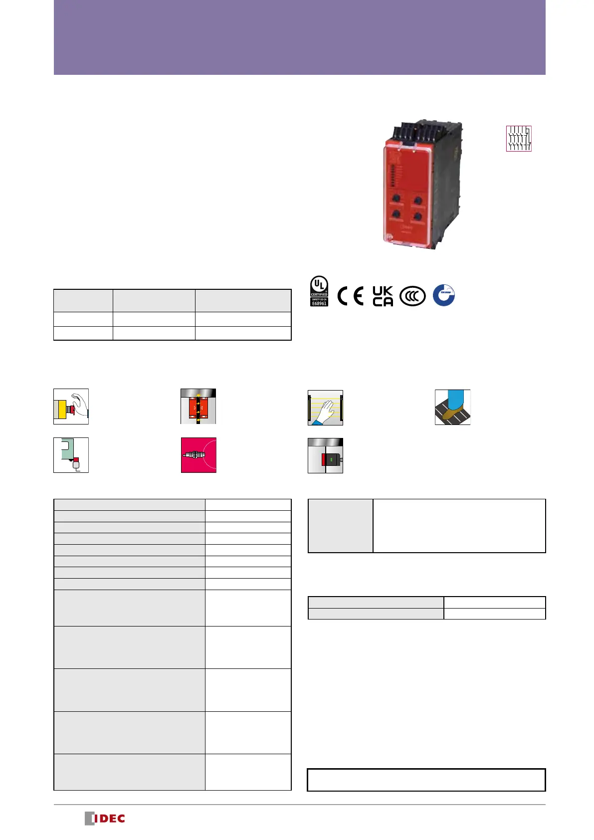
HR6S-AT Safety Relay Module
Safety-Related Outputs
Number of relay contacts, Normally Open, instantaneous 3
Number of relay contacts, Normally Open, delayed 3
Number of relay contacts, Normally Closed, delayed 1
Maximum short circuit current IK 1 kA
Maximum continuous current, Normally Open relay contacts
6 A
Maximum continuous current, Normally Closed relay contacts
3 A
Maximum total thermal current ∑I
THERM
12 A
Minimum current 10 mA
Utilization category as per UL 60947-5-1
B300 and R300 for Normally
Open contacts
D300 and R300 for Normally
Closed contacts
Utilization category as per IEC 60947-4-1 and
IEC 60947-5-1
AC-1: 250 V
AC-15: 250 V
DC-1: 24 V
DC-13: 24 V
Maximum current, normally open relay contacts
AC-1: 5 A
AC-15: 3 A
DC-1: 5 A
DC-13: 3 A
Maximum current, normally closed relay contacts
AC-1: 3 A
AC-15: 1 A
DC-1: 3 A
DC-13: 1 A
External fusing
10 A, category gG, for Normally
Open
4 A, category gG, for Normally
Closed
Additional Non-Safety-Related Outputs
Output voltage 24V DC
Maximum current 20 mA
Delay Times for Delay Function of Safety-Related Outputs
Possible values
0 s, 0.1 s, 0.2 s, 0.3 s, 0.4 s, 0.5 s, 0.6 s, 0.7 s,
0.8 s, 0.9 s, 1 s, 2 s, 3 s, 4 s, 5 s, 6 s, 7 s, 8 s,
9 s, 10 s, 20 s, 30 s, 40 s, 50 s, 60 s, 70 s, 80 s,
90 s, 100 s, 200 s, 300 s, 400 s, 500 s, 600 s,
700 s, 800 s, 900 s
Terminal Part No. Supply Voltage
Push-in terminal HR6S-AT1C 24V AC/DC
Screw terminal HR6S-AT1P 24V AC/DC
•
-One sealing strip (see page 28) is included with each product.
HR6S-AT Package Quantity: 1
Equipped with time delay output for Stop Category 0 and Stop Category 1
Synchronization Times
The synchronization times for the synchronization of safety-related
inputs depend on the application function. (See page 16 Function Mode
Selector and Input Device Connection Example.)
For other specifications (common to all models), see page 27.
Output expansion
possible
• See website for details on
approvals and standards.
S
a
f
e
t
y
A
p
p
r
o
v
e
d
H
R
6
S
*
-
1
4
3
5
.
I
M
.
1
3
5
0
0
5
/
2
0
TÜV NORD Systems
GmbH & Co.KG
 Loading...