13
HR6S Safety Relay Module
HR6S-AK
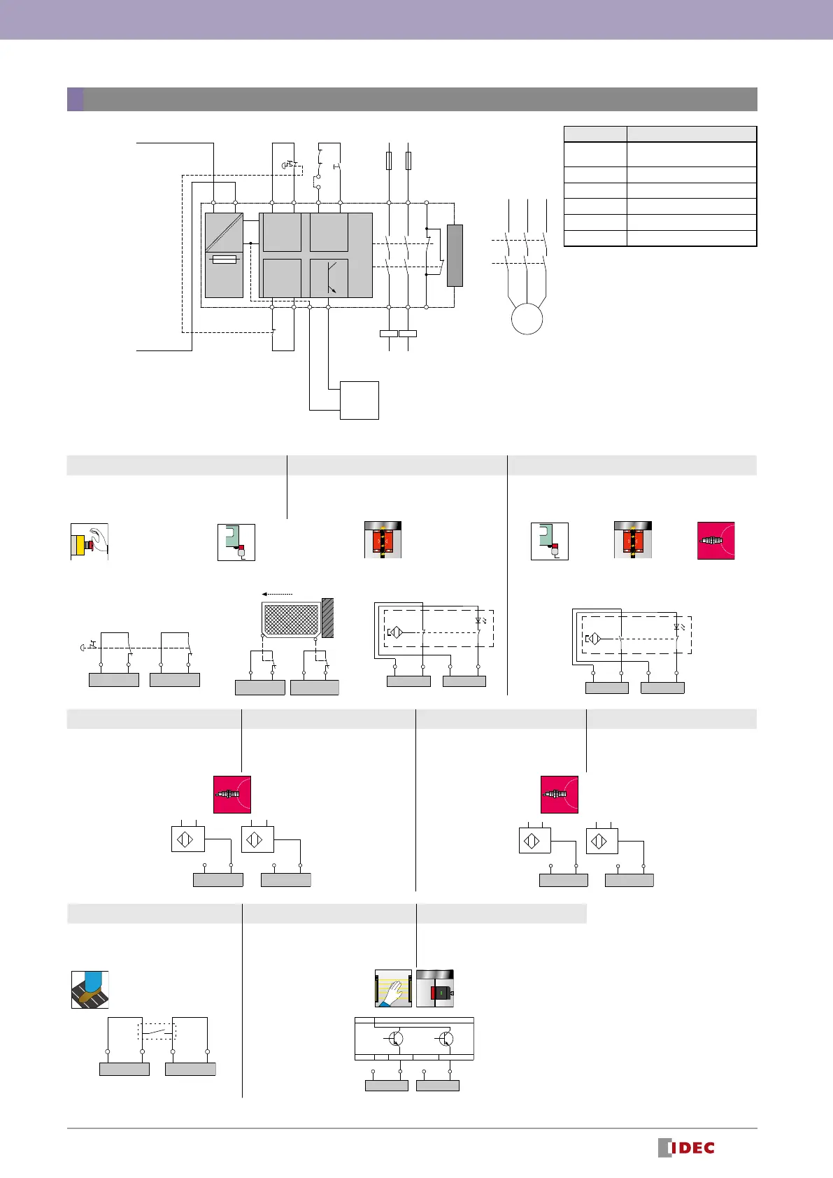
Function Mode Selector and Input Device Connection Example
Dial 1 Dial 2 Dial 3
Synchronous monitoring: No
Dynamization: Yes
Signal interlock monitoring: Yes
Synchronous monitoring: 2 s / 4 s (S12 rst / S22 rst
)
Dynamization: Yes
Signal interlock monitoring: Yes
Synchronous monitoring: 0.5 s
Dynamization: Yes
Signal interlock monitoring: No
Emergency stop
switches
Interlock switch
Coded magnetic
switch
(2 NO) (*2)
Interlock switch
(1 NO, 1 NC)
Coded magnetic switch
(1 NO, 1 NC)
(*2)
Proximity switch
(1 NO, 1 NC)
DC+ CH+ DC+ CH+
S11 S12 S21 S22
DC+ CH+ DC+ CH+
S12 S21
S22
DC+ CH+
S11 S12
DC+ CH+
S21 S22
DC+ CH+
S11 S12
DC+ CH+
S21 S22
Wiring
PLC
COM
(
0V
)
Input1
Common reference potential
(
0V
)
Semiconductor pulse output
(
DC24V
)
K3
K4
M
ESC
S1
S2
K3
K4
EXT
F1 F2
L1(
+
)
AC/DC
DC
DC+ CH+ DC+ CH+
CH+(-)DC+(-)
K1
K2
A1 A2 S11 S12 Y1 Y2
S21
S1
S22 Z1B2
N(
-
)
13
14
K3 K4
23
24
31
32
Input (*1)
StartInput
Power
supply
Dial 4 Dial 6 Dial 5 Dial 7
Synchronous monitoring: No
Dynamization: No
Signal interlock monitoring: Yes
Synchronous monitoring: 0.5 s
Dynamization: No
Signal interlock monitoring: Yes
Synchronous monitoring: No
Dynamization: No
Signal interlock monitoring: Yes
Synchronous monitoring: 0.5 s
Dynamization: No
Signal interlock monitoring: Yes
2 PNP 1 PNP + 1 NPN
DC+ CH+
S11 S12
A
A
DC+ CH+
S21 S22
PNP
PNP
DC+ CH+
S11 S12
A
A
DC- CH-
S21 S22
PNP NPN
Dial 8 Dial 9 Dial 10
Synchronous monitoring: No
Dynamization: No
Signal interlock monitoring: Yes
Synchronous monitoring: No
Dynamization: No
Signal interlock monitoring: Yes
Synchronous monitoring: 0.5 s
Dynamization: No
Signal interlock monitoring: Yes
Pressure-sensitive switch
2 OSSD
DC+ CH+ DC- CH-
S12 S21 S22
DC+ CH+ DC+ CH+
S11 S12
OSSD
0 V
ESPE
OSSD
S21 S22
*2:
Connection examples for coded magnetic switches such as HS7A (IDEC) are also included on the instruction sheet, but certications are not available.
Designation Explanation
EXT
Connector for optional
expansion module
S1 Emergency stop switch
S2 Start switch
K3, K4 Contactor
PLC Programmable controller
F1, F2 Fuse
*1:
The application function sets the negative
safe-related input according to the input
device.
 Loading...