9
HR6S Safety Relay Module
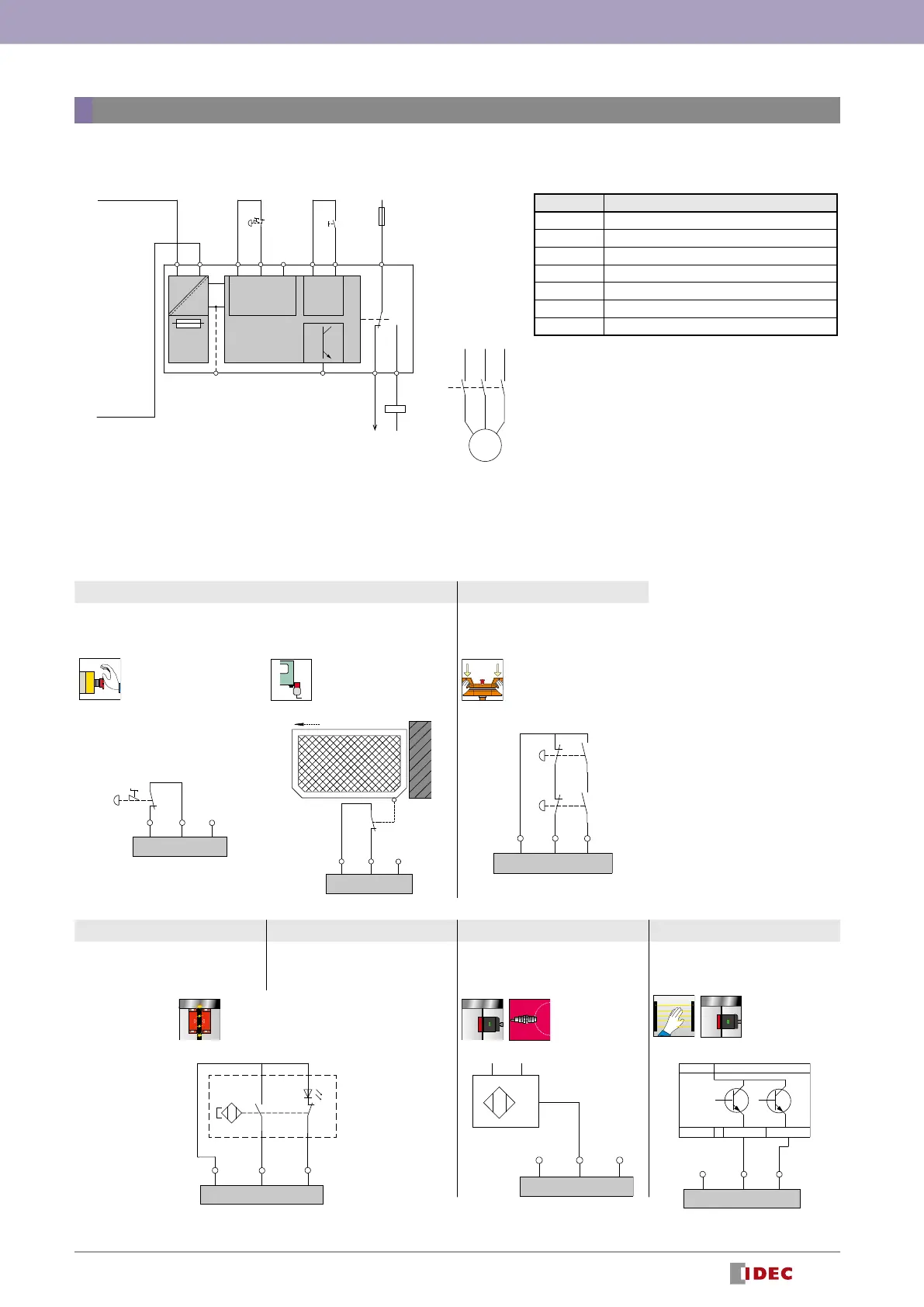
Wiring
Function Mode Selector and Input Device Connection Example
K2
K2
M
PLC
S1
12
AC/DC
DC
Power
supply
DC+
Input
CH+ CH+
K1
A1 A2 S11 S12 S13
S2
Start
DC+ CH+
Y1 Y2
B2(*1)
N (
-
)
14
F1
11
Z1(*1)
Dial 1 Dial 2
Synchronous monitoring: No
Dynamization: Yes
Signal interlock monitoring: No
Synchronous monitoring: 0.5 s
Dynamization: Yes
Signal interlock monitoring: No
Emergency stop switches Interlock switch Two-hand control switch
(IIIA)
DC+ CH+ CH+
S11 S12 S13
DC+ CH+ CH+
S11 S12 S13
DC+ CH+ CH+
S11 S12 S13
S1
S2
Dial 3 Dial 4 Dial 5 Dial 6
Synchronous monitoring: 0.5 s
Dynamization: Yes
Signal interlock monitoring: No
Synchronous monitoring: 2.2 s
Dynamization: Yes
Signal interlock monitoring: No
Synchronous monitoring: No
Dynamization: No
Signal interlock monitoring: No
Synchronous monitoring: 0.5 s
Dynamization: No
Signal interlock monitoring: Yes
Coded magnetic switch (*2)
(1NO, 1NC)
1 PNP output
device
2 OSSD
Output device
DC+ CH+
S1
S12
CH+
S13
DC+ CH+
S11 S12
+
-
CH+
S13
PNP
DC+ CH+ CH+
S11 S12
OSSD
0 V
ESPE
24 V
OSSD
S13
*2: Connection examples for coded magnetic switches such as HS7A (IDEC) are also included on the instruction sheet, but certications are not available.
Note: Status of contacts in the diagram: The status of the control switch is when it is not operated. The status of the door interlock is when the door is closed.
HR6S-AB
Designation Explanation
B2 Common reference potential terminal
Z1 Pulsed output for diagnostics, not safety-related
S1 Emergency stop switch
S2 Start switch
K2 Contactor
M Motor
F1 Fuse
*1) For B2 and Z1, see HR6S-AF.