B-1715(3)
INSTRUCTION SHEET - HS5L Series Solenoid Type Safety Switch
( 2 / 8 )
2016.04
3
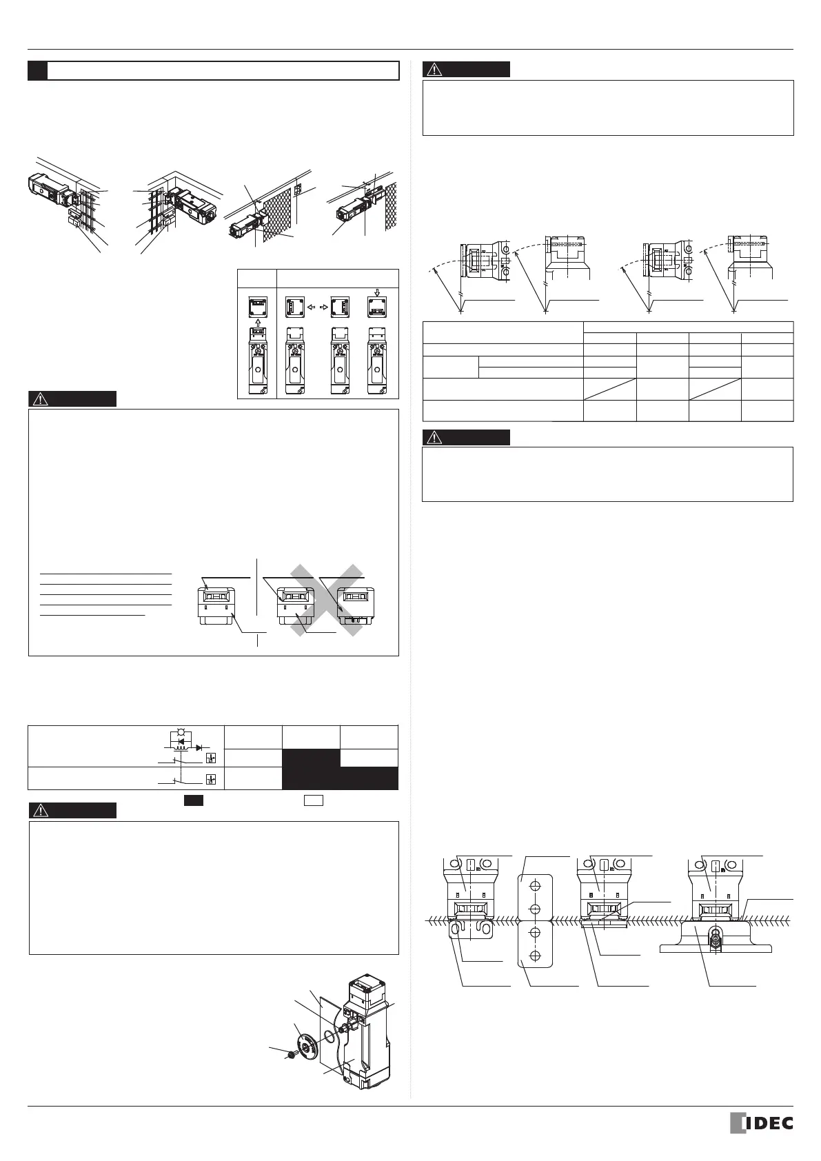
Mounting Examples
• Install the interlock switch on the immovable machine or guard, and install the
actuator on the movable door. Do not install both interlock switch and actuator on
the movable door, otherwise the angle of insertion of the actuator to the safety switch
may become inappropriate, and failure will occur.
HS5L Head Removal Detection Function (Only Spring Lock Type)
• When the actuator is operated, the operation of the monitor circuit (11-42) and
(51-52) are the same.However, when the head is removed, disparity is detected
(11-42: OFF, 51-52: ON). The disparity of the contacts detects the removal of the
head.
• The Head Removal Detection Function cannot be used with HS5L solenoid lock
type products.
• When the head is removed from the device (e.g. when changing the mounting
position of the head), the 41-42 lock monitor circuit opens (OFF position) and
51-52 monitor circuits close (ON position); so please make sure you connect the
41-42 lock monitor circuit to a safety circuit if you want to use the Head Removal
Detection Function.
• The Head Removal Detection Function can only be used with the following
spring-lock circuits: A,B,C,D,F,G, J, DD, VB, VD, VJ, TB, TD and TJ type circuits
(lock monitor circuit NC: 2 circuits or more, excluding XH). This function cannot be
used with other spring-lock type circuits and solenoid circuits.
(Examples of Mounting on Sliding Doors)
HS9Z-A51
Actuator
Door Stop
Latch
HS5L
Safety Switch
Door
(Examples of Mounting on Hinged Doors)
HS9Z-A52
Actuator
HS5L
Safety Switch
HS9Z-SH5
Slide Actuator
Door
The HS5L Head
• Changing the Mounting Directions of the
HS5L Head
The head of the HS5L can be mounted
in four directions by removing the four
screws from the corners of the HS5L
head.
When
Shipped
Alternative Mounting Directions
Mounting Directions of the HS5L Head
• Before changing he mounting direction of the HS5L head, turn the manual unlock
to UNLOCK using the attached manual unlock key or disconnect wiring from the
HS5L.
• If the head position is changed after wiring without taking the above action, the
machine may start to operate and the worker may face danger.
• When replacing the HS5L head, make sure that no foreign object enters into the
safety switch. Tighten the screws tightly, without leaving space between the head
and body, otherwise the safety switch may malfunction.
• Don't remove the screws of head except when the mounting directions of head is
changed.
Mounting the Head
• Do not use the metallic or
plastic head for the HS5D
(without lock type). Be sure to
use the head for the HS5L and
mount he correct head.
Take care particularly when
using with the HS5D (without
lock type).
HS5DHS5L
Metallic Head Metallic Head
Plastic
Color : Red
Color:
Red
Color:
Black
Plastic Head
Metallic
Color : Silver
Metallic
Color : Silver
5251
41
Lock Monitor Circuit (NC)
Lock Monitor Circuit (NC)
42
A1
A2
HEAD
REMOVE
ACTUATOR
UNLOCK
ACTUATOR
LOCK
:Contact Closed :Contact Open
(+) (
-
)
• After installing the rear unlock button, apply Loctite to the screw so that the screw
does not become loose. The lod is made of stainless steel.The rear unlock button
is glass-reinforced PA66 (66 nylon). The mounting screw is iron. Take the
compatibility of plastic material and Loctite into consideration.
HS9Z-A52
HS9Z-A52
Mounting centers:12 mm
Mounting centers:20 mm
HS9Z-A53
HS9Z-A55
R1
230 mm
230 mm
310 mm
70 mm
(Horizontal Swing)
R2
260 mm
260 mm
80 mm
(Vertical Swing)
70 mm
(Vertical Swing)
R3
170 mm
120 mm
170 mm
50 mm
(Horizontal Swing)
R4
190 mm
140 mm
50 mm
(Vertical Swing)
50 mm
(Vertical Swing)
Minimum Radius
• The values shown above are based on the condition that the actuator enters and
exits the actuator entry slot smoothly when the door is closed or opened. Since
there may be deviation or dislocation of the hinged door, make sure of correct
operation in the actual application before installation.
Adjusting the Angle Adjustable (vertical/horizontal) Actuator
(Type HS9Z-A53/A55)
• Using the angle adjustment screw (M3 hexagon socket set screw), the actuator angle
can be adjusted up to 20°(refer to dimensions).
• The larger the actuator angle, the smaller the applicable radius of the door swing.
After installing the actuator, open the door. Then adjust the actuator angle so that the
actuator enters the entry slot of the safety switch properly.
• After adjusting the actuator angle, apply loctite or the like on the adjustment screw to
prevent loosening.
(Type HS9Z-A53)
Tightening torque of angle adjustment screw : 0.8 N•m.
(Type HS9Z-A55)
Use screw locking agent hat is compatible with the base material.
Base : PA66 (66 nylon) of glass reinforced grade
Angle adjustment screws : stainless steel
Actuator Mounting Reference Position
As shown below, the mounting reference position of the actuator inserted into the
safety switch is:
(Type HS9Z-A53)
The actuator stop film placed on the actuator touches the safety switch lightly.
(Except Type HS9Z-A53)
The actuator and actuator cover touches the actuator stop placed on the safety
switch lightly.
(After mounting the actuator, remove the actuator stop from the safety switch.)
Actuator Mounting Tolerance
• Mounting tolerance of the actuator is 1.0 mm in the four lateral directions.
• Make sure the actuator can be inserted into the entry slot wi hout any issue.
• When closing the door, the actuator is inserted and locked within a certain distance
from the reference position. After the actuator has been locked, the contact operation
is not affected by the actuator movement in the locked state.
• When using the safety switch for a hinged door, the minimum radius of the applicable
door is shown in the following figures.
Minimum Radius of Hinged Door
Installing the Rear Unlock Button
(Type HS5L-
□L)
• After installing the interlock switch on
the panel, put the rear unlock button
(supplied) on the rod on the back of the
interlock switch, and fasten using the
mounting screw. When installing on the
aluminum frame of the thickness of
6mm or more, use the rear unlock
button for frame kit (HS9Z-FL5
□) sold
separately.
HS5L-□L
Safety switch
The Rear Unlock
Button
Mounting
Screw
(M3 sems screw)
Panel
Rod
When the center of the hinged door is
on the extension line of the actuator
mounting surfase.
When the center of he hinged door is
on the extension line of the contact surface
of actuator and safety switch.
Door Hinge Door Hinge
Minimum
Radius
Minimum Radius
R1
R2
Door Hinge Door Hinge
Minimum Radius
Minimum
Radius
R4
R3
Actuator
Stop
Actuator
Stop
Actuator
Cover
Stop Film
Door Stop
Safety Switch
Safety Switch
Safety Switch
HS9Z-A51
Actuator
HS9Z-A52
Actuator
HS9Z-A53
ActuatorDoor Stop
 Loading...