B-1715(3)
INSTRUCTION SHEET - HS5L Series Solenoid Type Safety Switch
( 4 / 8 )
2016.04
5
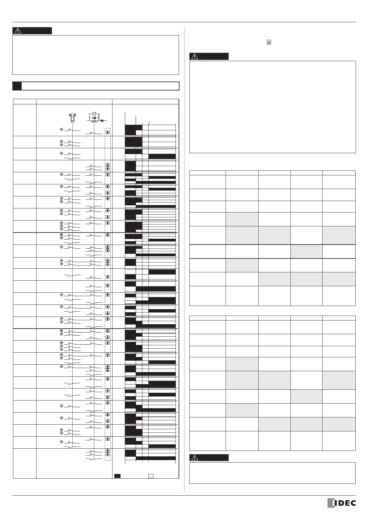
Contact Operation
(Actuator
Completely Inserted)
(Actuator
Pulled Out)
Contact Operation (reference)Type *10 Contact Congifiguration *11
A1A2
(+) (
-
)
*9
[HS5L-TJ□]
[HS5L-TG□]
[HS5L-TF□]
[HS5L-TD□]
[HS5L-TC□]
[HS5L-TB□]
[HS5L-TA□]
[HS5L-J□]
[HS5L-G□]
[HS5L-F□]
[HS5L-D□]
[HS5L-C□]
[HS5L-B□]
[HS5L-A□]
[HS5L-XB□]
HS5L-DD□
HS5L-VG□
HS5L-VF□
HS5L-VD□
HS5L-VC□
HS5L-VB□
HS5L-VA□
HS5L-XH□
HS5L-XG□
HS5L-XF□
HS5L-XD□
Main Circuit:
Monitor Circuit:
Monitor Circuit:
11
23 24
53 54
42
11-42
23-24
53-54
23
11
24
51 52
42
Main Circuit:
Monitor Circuit:
Monitor Circuit:
11-42
23-24
51-52
11
21 22
53
42
54
Main Circuit:
Monitor Circuit:
Monitor Circuit:
11-42
21-22
53-54
11
21 22
51
42
52
Main Circuit:
Monitor Circuit:
Monitor Circuit:
11-42
21-22
51-52
11
21
33
22
34
42
Main Circuit:
Monitor Circuit:
Monitor Circuit:
11-42
21-22
33-34
11
21
31
22
32
42
Main Circuit:
Monitor Circuit:
Monitor Circuit:
11-42
21-22
31-32
11
63
51
64
52
42
Main Circuit:
Monitor Circuit:
Monitor Circuit:
11-42
51-52
63-64
21
11 42
52
Main Circuit:
Main Circuit:
11-42
21-52
23
11 12
24
41
53
42
54
Monitor Circuit:
Monitor Circuit:
Monitor Circuit:
11-12
23-24
41-42
53-54
11
23 24
12 41
51
42
52
Monitor Circuit:
Monitor Circuit:
Monitor Circuit:
11-12
23-24
41-42
51-52
21
11 12
22
53
41
54
42
Monitor Circuit:
Monitor Circuit:
Monitor Circuit:
11-12
21-22
41-42
53-54
21
11
22
12
51
41
52
42
Monitor Circuit:
Monitor Circuit:
Monitor Circuit:
11-12
21-22
41-42
51-52
31
21
11
32
22
12 41 42
Monitor Circuit:
Monitor Circuit:
Monitor Circuit:
11-12
21-22
31-32
41-42
33
21
11
34
22
12 41 42
Monitor Circuit:
Monitor Circuit:
Monitor Circuit:
11-12
21-22
33-34
41-42
11
21
12
22
Monitor Circuit:
Monitor Circuit:
11-12
21-22
11
23
12
24
Monitor Circuit:
Monitor Circuit:
11-12
23-24
51
41
52
42
Monitor Circuit:
Monitor Circuit:
41-42
51-52
11 12
41 42
Monitor Circuit:
Monitor Circuit:
11-12
41-42
13 14
41 42
Monitor Circuit:
Monitor Circuit:
13-14
41-42
13 14
53 54
Monitor Circuit:
Monitor Circuit:
Monitor Circuit:
41-42
13-14
53-54
41 42
11 12
51 52
Monitor Circuit:
Monitor Circuit:
Monitor Circuit:
41-42
11-12
51-52
41 42
21
11
22
12
Monitor Circuit:
Monitor Circuit:
Monitor Circuit:
41-42
11-12
21-22
41 42
63
51
64
52
Monitor Circuit:
Monitor Circuit:
Monitor Circuit:
41-42
51-52
63-64
41
42
23
11
24
12
Monitor Circuit:
Monitor Circuit:
Monitor Circuit:
41-42
11-12
23-24
41 42
14
51 52
Monitor Circuit:
Monitor Circuit:
Monitor Circuit:
41-42
13-14
51-52
41 42
13
11 12
53 54
Monitor Circuit:
Monitor Circuit:
Monitor Circuit:
41-42
11-12
53-54
41 42
HS5L-VJ□
11 12
63
51
41
64
52
42
Monitor Circuit:
Monitor Circuit:
Monitor Circuit:
11-12
41-42
51-52
63-64
[HS5L-XJ□]
53
41
54
42
Monitor Circuit:
Monitor Circuit:
41-42
53-54
:Contact Closed
:Contact Open
Contact Configuration and Operation
Approx. 3 3 (Lock)
0
(Actuator Mounting Reference Position)
Approx.
26.4
Approx
5 3
Approx.
6.9
(Travel: mm)
• Contact operation is based on the condition that the actuator is inserted into the
center of the safety switch slot.
• Contact operation shows the HS9Z-A51 actuator.
(For other actuators, add 1.3 mm to contact operation.)
• Use main circuit or monitor circuit with for the input to safety circuit.
• Indicator turns on when solenoid is energized.
• Install the HS5L to ensure that a worker can operate the rear unlock button from
inside the safety hedge (the dangerous area). It is dangerous to install the HS5L in
the position where the rear unlock button can be operated from outside the the
safety hedge (the dangerous area), because it is possible to unlock while the
machine is operating.
• Use hand to press the button, and do not use a tool. Do not apply excessive force
to he rear unlock button.
*12 Do not attempt manual unlocking when the solenoid is energized.
*13 Do not energize the solenoid for a long time while the door is open or when the
door is unlocked manually.
*9 This locking monitoring marking has been newly described in section 9.2.1 of
EN ISO / ISO14119. It indicates that any devices with this marking meet the
following EN ISO / ISO 14119 requirements:
- General (- General requirements for guard locking devices) (Section 5.7.1) *
- Locking monitoring (- Locking monitoring for guard locking devices) (Section
5.7.2.2)
When a lock monitor circuit (contact) has the locking monitoring marking, it
means that one circuit (contact) can monitor the position and the locking
function of the protective door. (The locking monitoring circuit (contact) turns
ON only when the protective door is closed and locked.)
*note Both types of HS5L safety switches - spring lock type switches and solenoid
lock type switches - have obtained the locking monitoring cer ification marking.
Based on risk assessment results, solenoid lock type switches can be used
only for limited applications which do not especially need to be locked for
safety.
*10 Type No. in [ ] are not supplied as standard. See 1. Type for standard.
*11 These are the image of locking position with actuator inserted.
• Solenoid Lock Type (HS5L-□7Y)
Main Circuit
11-42
21-52
Monitor Circuit
11-12
21-22
31-32
Monitor Circuit
23-24
33-34
Monitor Circuit
41-42
51-52
Monitor Circuit
53-54
63-64
Door is
locked.
The machine
can be
operated.
Door is
unlocked.
The machine
can not be
operated.
The machine
can not be
operated.
Door is
unlocked.
The machine
can not be
operated.
Open
OFF/ON
*13
Closed
Turn the
key to unlock
position
Turn the
key to lock
posi ion
Returned
status
When
opera ing
he Button
Closed
Closed Closed Closed
Closed
Closed
Closed
Closed
Closed
Open
Open
Open
Open
Open Open Open
Open
Open
Open
Open
OFF
*12 *13
Manual
Unlock Key
Rear Unlock
Button
Closed
OFFON
Closed
Turn he
key to lock
position
Turn the
key to lock
position
Returned
status
Returned
status
Door States
Solenoid
Power
A1-A2
Operation Cycle
• Spring Lock Type (HS5L-□4)
Manual
Unlock Key
Rear Unlock
Button
Main Circuit
11-42
21-52
Monitor Circuit
11-12
21-22
31-32
Monitor Circuit
23-24
33-34
Monitor Circuit
41-42
51-52
Monitor Circuit
53-54
63-64
Door is
locked.
The machine
can be
operated.
Door is
unlocked.
The machine
can not be
operated.
The machine
can not be
operated.
Door is
unlocked.
The machine
can not be
operated.
Closed
Open
OFF ON
ON/OFF
Closed Closed
OFF
Turn he
key to lock
position
Turn the
key to unlock
position
Turn the
key to lock
position
Turn the
key to lock
posi ion
Returned
status
Returned
status
Returned
status
When
opera ing
he Button
Closed
Closed Closed Closed
Closed
Closed
Closed
Closed
Closed
Open
Open
Open
Open
Open Open Open
Open
Open
Open
Open
Door States
Solenoid
Power
A1-A2
 Loading...