B-1715(3)
INSTRUCTION SHEET - HS5L Series Solenoid Type Safety Switch
( 5 / 8 )
2016.04
Note : Confirm the outside diameter of the multi-core cable, the connector type
depends on the outside diameter of multi-core cable.
Note : When using ST-M20×1.5, use with gasket GP-M (Type No: GPM20, made by
LAPP).
Note : If you use HS5L as Type 4X, please use M20 connectors that are certified the
following.
Plastic connector: Type 4,4X, 6 or 6P
Metal connector: Type 4X or 6P
• Wiring Instructions
1. Insert the applicable screwdriver into
the square-shaped port as shown,until
the screwdriver tip touches the bottom
of the spring.
3. While the screwdriver is retained in
the port, insert the wire or ferrule into
the round-shaped wire port. Each wire
port can accommodate one wire or
ferrule.
2. Push in the screwdriver until it
touches the bottom of the port. The
wire port is now open, and the
screwdriver is held in place. The
screwdriver will not come off even if
you release your hand.
4. Pull out the screwdriver. The
connection is now complete.
• In applications using ferrules for stranded wires, choose the ferrule listed in the table.
mm
2
AI0.5-6WH
AI0.75-6GY
AI1-6RD
TE0.5-8
TE0.75-8
TE1.0-8
0.5
0.75
1
0.5
0.75
1
AWG
AI0.34-6TQ
0.34
20
18
18
20
18
18
22
Phoenix
Contact
Nichifu
Part No.
Manufacturer
Applicable wire
(stranded)
6
Wiring
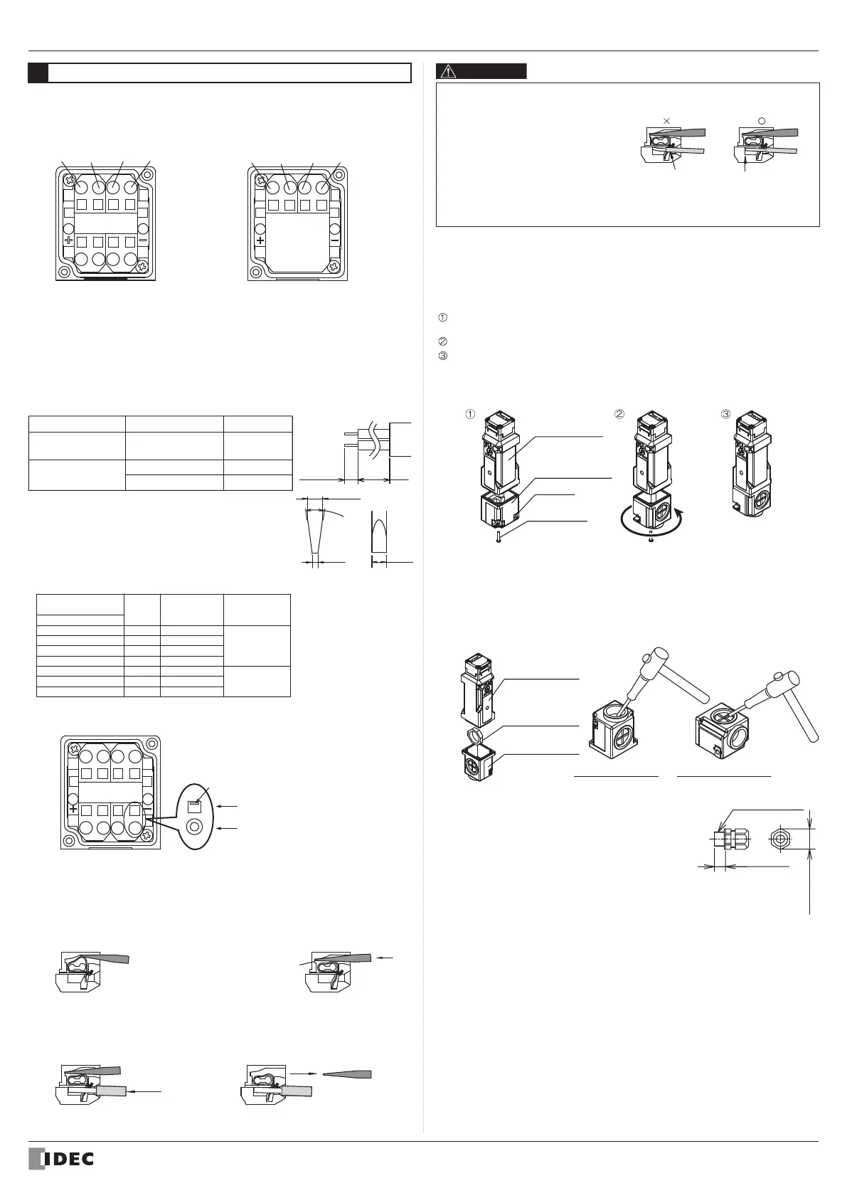
Terminal wiring method
• Terminal NO.
‹4 contact type› ‹2 contact type›
21/23/
41/43
22/24/
42/44
11/13/
51/53
12/14/
52/54
A1A2
1211 4241
A1
A2
31/33/
51/53
32/34/
52/54
21/23/
63
22/24/
64
• Wire insertion positions, screwdriver insertion positions, and the directions of
screwdriver tip are shown below.
A1
A2
The round-shaped Wire Port
The square-shaped Screwdriver
Port Direction of Screwdriver Tip
Screwdriver Tip
Bottom of the Port
Note :
•
The following type circuits are shipped with jumpers connecting the indicated terminals.
A,B,C,D,F,G,J type circuits: Jumper connecting 12-41
DD type circuit: Jumpers connecting 12-41 and 22-51
•
When the NC contacts (11-12)/(21-22) of the door monitor circuit and NC contacts
(41-42)/(51-52) of the lock monitor circuit are connected in series as inputs to the safety
circuit, connect 12-41 or 22-51 before use.
• Wire length and example of layout
• Recommended Wire Core Size : 0.3 to 1.5 mm
2
(AWG22 to 16)
Routing direction
Wire Length: L1
Type
HS5L-□△
*
4LM-G
HS5L-
□△
*
4M-G
HS5L-
□△
*
4LSM-G
HS5L-
□△
*
4SM-G
Straight orientation
Straight orientation
Horizontal orientation
30 to 35mm
50 to 55mm
40 to 45mm
8 to 9mm
L1
• For wiring, use the following applicable screwdriver.
(Tip shape of the driver is according to the standard of
DIN5264)
0.4
7° t o 13°
Φ2.5
2.5
How to open conduit port (cable side-routed type)
• Before use, knock in the conduit port where the connector is to be connected, using
a tool such as screwdriver as shown in the figures.
• Before opening the conduit port, remove the terminal cover from the HS5L Safety
Switch main unit, and remove the locking ring for the cable gland installed in the
terminal cover.
• Be sure to remove any crack or burrs on the conduit port, as it will impair waterproof
performance.
Safety switch
Straight orientation Horizontal orientation
Locking ring
for cable gland
Terminal cover
How to change the cable routing direction (cable side-routed type)
When using a cable side-routed type (HS5L-□△*SM-G), you can select from three
orientations (straight, left and right) as the wiring direction. When the unit is shipped,
the cover is installed so that wiring can be routed straight or in the left orientation.
When using the unit with the wiring in the right orientation, refit the cover by the
procedure below.
Remove the cover mounting screws (M3 screws x 2), and remove the cover from
the HS5L Safety Switch main unit.
Rotate the terminal cover 180 degrees as shown in the figure.
Install the cover on the Safety Switch, and secure it in place with the cover
moun ing screws (M3 screws x 2).
* Before tightening the cover mounting screws, slide the spacer in the direction
opposite the screw positions to prevent it from coming into contact with the
screwdriver.
Safety switch
Terminal cover
Spacer
M3 screws
180
°
Use a connector with a degree of protection IP67.
Applicable connector dimensions : See the figure on the right.
• When using flexible conduit and metal connector
Applicable Flexible Conduit Example:
Type VF-03 (made by Nihon Flex)
(M20) Applicable Metal Connector Example:
Type RLC-103EC20 (made by Nihon Flex)
• When using plastic connector, metal connector and multi-core cable
(M20) Applicable Plastic Connector Example:
Type ST-M20×1.5 (made by LAPP)
Applicable Metal Connector Example:
Type ALS-
□□EC20 (made by Nihon Flex)
9mm max.
Conduit Thread
30mm max.
Applicable Connectors
Correct
The wire is inserted
deep enough
between the clamps
Incorrect
The wire insulation
shea h is in contact
wi h the clamps
• When using wire with insulation
diameter of Φ2.0mm or less, do not
insert the wire too deep where the
insulation inserts into the spring clamp
opening. Otherwise conductive failure
will be caused. Make sure that the
wire insulation is stripped 8 to 9 mm
and the wire is inserted to the bottom.
• Please only connect one wire per
terminal port (according to the general
requirements section (13.1.1) of
IEC60204).
 Loading...