( 8 / 8 )
B-1715(3)
INSTRUCTION SHEET - HS5L Series Solenoid Type Safety Switch
2016.04
9
Precaution for Disposal
Dispose of the HS5L safety switch as an industrial waste.
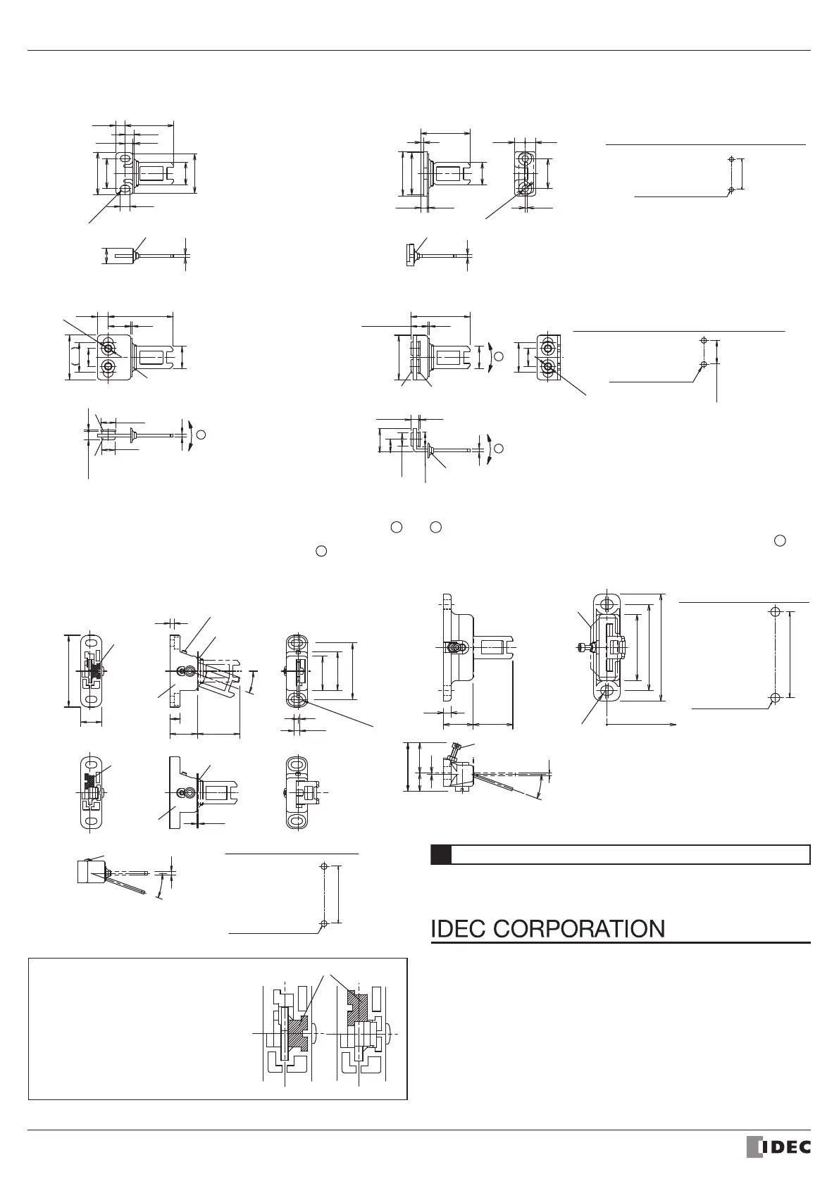
*14 The actuator stop and The Stopper film
are used when adjusting the actuator
position. Remove after the actuator
position is determined.
*15 The direction of adjustable angle can be
changed (vertical or horizontal) by
changing the insertion direction of the
joint (white plastic part).Do not lose the
joints. Actuators do not operatenormally
without a joint.
Type : HS9Z-A53Type : HS9Z-A55
D
2-Φ9
2-Φ10
0 8
( 20
0.8 12
2
2-Φ4.3
15
15 3
43 87.3
30
20
12 or 20
Accessories dimensions
Type : HS9Z-A51
2
6.4
6 2
(6)
5.2 0.8
10
4-R 2.2
20
32.4
15
26
28
Actuator Stop *14
(Supplied with actuator)
(To be sold by separately)
Type : HS9Z-A52
1.6
7 2 7 22
4.5 0 8
15
28
29.6
33
20
2-Φ
4.4
2
Actuator Stop *14
(Supplied with actuator)
Type : HS9Z-A52AType : HS9Z-A51A
* Make sure to use the product with the moun ing pitch at either 12 mm
or 20 mm.
*Mounting pitch is set to 12 mm in factory. When setting the mounting
pitch to 20 mm, widen he pitch of rubber cushions to 20 mm.
* The actuator has movement flexibility to the direc ions shown in D .
Actuator Stop *14
(Supplied with actuator)
Rubber Cushions
Washer(Supplied with actuator)
the door(5)
When installed on
* Make sure to use the product with the moun ing pitch at either 12 mm or 20 mm.
* When the mounting pitch is 12 mm (factory setting), the actuator has movement flexibility to the directions
shown in C and D .
* When the mounting pitch is 20 mm, he actuator has movement flexibility to the directions shown in D . Side
the rubber cushions together with the screws.
C
D
( 20 )
12
2-Φ4.3
2-Φ10
2-Φ9
0 8
2
0.8
8 5
15.8
15
30
2-M4
(Φ4.3 or M4 tapped)
when installed
on the door(5)
When installed
on the door(39.7)
When installed
on the door(11.2)
Rubber Cushions
Washer(Supplied with actuator)
Actuator Stop *14
(Supplied with actuator)
HS9Z-A51A/A52A Actuator mounting hole layout
HS9Z-A51/A52 Actuator mounting hole layout
2-M4
(Φ4.3 or M4 tapped)
MAX 33
R3.2
5
20
72
58
44
29
12 (21)
20°
1
58
2
Stopper Film *14
(Supplied with actuator)
Rotation center
side of door
Angle adjusting screw
(M3 hexagon socket bolt)
2-M6
(Φ6.3 or M6 tapped)
Actuator mounting hole layout
0.8
20°
2
3.6
1
20°
28.518.5
3
7
14.4
48.4
38
26
23
Joint
Base
38
R2 1
(Horizontal adjustment
) *15
(Vertical adjustment
) *15
Angle Adjusting Screw
(M3 hexagon socket set screw)
Actuator Stop
*14
(Supplied with actuator)
2-M4
(Φ4.3 or M4 tapped)
Actuator mounting hole layout
( M4 holes )
Actuator stop
*14
(Supplied with actuator)
Base
Joint
Angle adjusting screw
(M3 hexagon socket set screw)
(horizontal adjustment) (vertical adjustment)
Joint
http://www.idec.com
Manufacturer: IDEC CORP.
2-6-64 Nishimiyahara Yodogawa-ku, Osaka 532-0004, Japan
EU Authorized Representative:IDEC Elektrotechnik GmbH
Heselstuecken 8, D-22453 Hamburg, Germany
DECLARATION OF CONFORMITY
We, IDEC CORPORATION 2-6-64, Nishimiyahara Yodogawa-ku,Osaka 532-0004, Japan declare
under our sole responsibility that the product:
Description: Safety Switch
Model No: HS5L
to which this declaration relates is in conformity with the EC Directive on the following standard(s)
or other normative document(s). In case of alteration of the product, not agreed upon by us, this
declaration will lose its validity.
Applicable EC Directive : Low Voltage Directive, 2006/95/EC (until April 19th, 2016),
Low Voltage Directive, 2014/35/EU (from April 20th, 2016),
Machinery Directive (2006/42/EC)
Applicable Standard(s) : EN 60947-5-1,GS-ET-19
 Loading...