3: I
NSTALLATION
AND
W
IRING
3-26 FC6A S
ERIES
MICROS
MART
U
SER
’
S
M
ANUAL
FC9Y-B1722
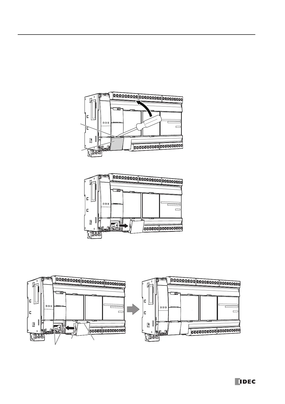
Removing and Attaching the Ethernet Port 1 Cover
The following procedure describes how to remove and attach the Ethernet port 1 cover. The procedure is the same for Ethernet
port 1 cover and Ethernet port 2 cover on the Plus CPU module.
Removing the Ethernet Port 1 Cover
1. Insert a flathead screwdriver into the screwdriver slot on the Ethernet port 1 cover and slowly move the screwdriver in the
direction of the arrow to unlock the top lock.
2. Lift the Ethernet port 1 cover straight up in the direction of the arrow to remove it.
Attaching the Ethernet Port 1 Cover
When not using Ethernet port 1, attach the Ethernet port 1 cover.
1. Insert the Ethernet port 1 cover tabs into the grooves on the left and right sides of Ethernet port 1 and push the cover straight
in to attach it.
Note: Take care with the orientation of the Ethernet port 1 cover. The groove to insert the screwdriver goes on the bottom.
Ethernet Port 1 Cover
Screwdriver Slot
Tab
Screwdriver Slot Groove
Ethernet Port 1 Groove
 Loading...
