3: I
NSTALLATION
AND
W
IRING
3-40 FC6A S
ERIES
MICROS
MART
U
SER
’
S
M
ANUAL
FC9Y-B1722
*1 Not included in the calculation of the connection restriction.
*2 There is no change in the current of the internal power supply for the cartridge base module, even if cartridges are connected.
*3 Current for the backlight. This is not included in the calculation of the connection restriction.
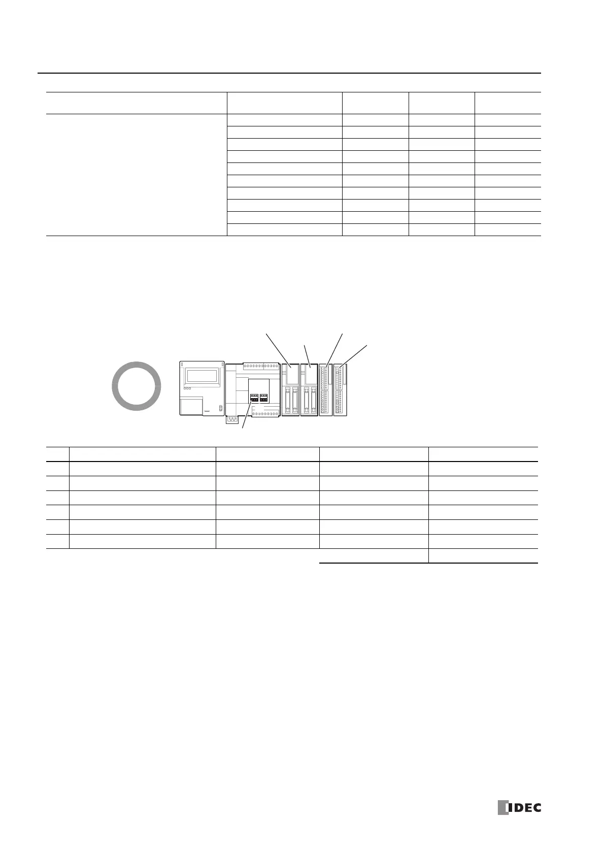
■ Connection Example 1
This example describes the number of connected modules, the internal 5 V line current, and the internal 24 V line current when
the expansion modules, HMI module, and cartridges in the below diagram are connected to the 16-I/O type.
Number of connected modules
For the 16-I/O type, the number of modules that can be connected must be four expansion modules (basic expansion side),
one HMI module, and two cartridges or lower. There are four expansion modules (basic expansion side), one HMI module,
and one cartridge, so there is no problem because the maximum number of modules was not exceeded.
Internal 5 V line current
The current must be 695 mA or lower. The total current is 415 mA, so there is no problem because it is not exceeded 695 mA.
Internal 24 V line current
The current must be 126 mA or lower. The total current is 48 mA, so there is no problem because it is not exceeded 126 mA.
HMI module + cartridge
FC6A-PH1+FC6A-PJ2A ― 170 mA 15 mA
*3
FC6A-PH1+FC6A-PJ2CP ― 170 mA 15 mA
*3
FC6A-PH1+FC6A-PK2AV ― 250 mA 15 mA
*3
FC6A-PH1+FC6A-PK2AW ― 360 mA 15 mA
*3
FC6A-PH1+FC6A-PC1 ― 180 mA 15 mA
*3
FC6A-PH1+FC6A-PC3 ― 230 mA 15 mA
*3
FC6A-PH1+FC6A-PC4 ― 290 mA 15 mA
*3
FC6A-PH1+FC6A-PN4 ― 175 mA 15 mA
*3
FC6A-PH1+FC6A-PTK4 ― 175 mA 15 mA
*3
FC6A-PH1+FC6A-PTS4 ― 175 mA 15 mA
*3
No. Module Type Model Internal 5 V Line Current Internal 24 V Line Current
(1) HMI Module (no installed cartridges) FC6A-PH1 150 mA ―
(2) Communication Cartridge FC6A-PC3 60 mA ―
(3) Digital Output Module FC6A-T32P3 45 mA 48 mA (= 1.5 mA × 32 points)
(4) Digital Input Module FC6A-N32B3 65 mA ―
(5) Analog Input Module FC6A-J4CN1 50 mA ―
(6) Analog Input Module FC6A-J4A1 45 mA ―
415 mA (695 mA or lower) 48 mA (126 mA or lower)
Module Type Model
Internal 3.3 V
Line Current
*1
Internal 5 V
Line Current
Internal 24 V
Line Current
FC6A-T32P3
FC6A-PC3
FC6A-PH1
(1)
FC6A
-C16P1CE
(2)
(3) (4) (5) (6)
FC6A-N32B3
FC6A-J4CN1
FC6A-J4A1
 Loading...
