FC6A S
ERIES
MICROS
MART
U
SER
’
S
M
ANUAL
FC9Y-B1722 3-43
3: I
NSTALLATION
AND
W
IRING
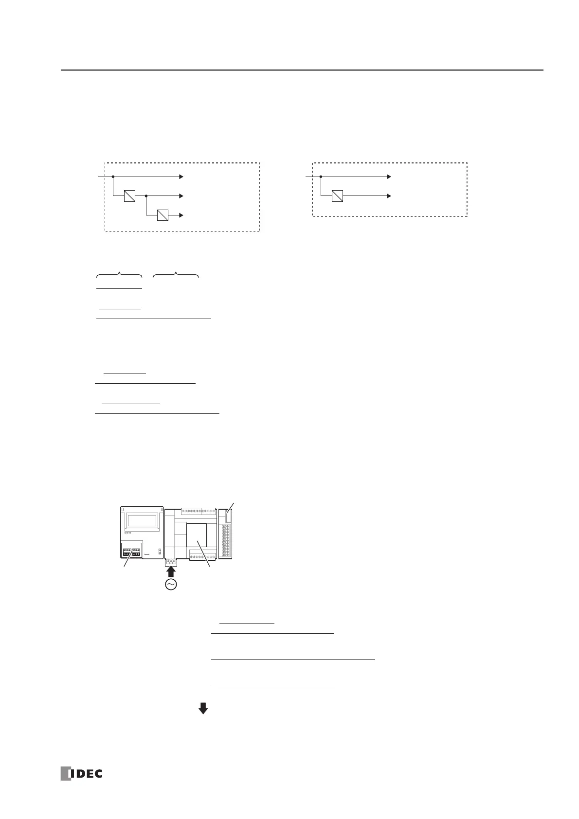
When the FC6A-R081 or FC6A-PC4 is connected to the Plus CPU module or an expansion interface module
Calculate the voltage conversion in the CPU module and expansion interface module with the following efficiencies.
For the FC6A-R081
For the FC6A-PC4
*1
*1 Cartridges cannot be connected to expansion interface modules.
■ Example 1 of Calculating the Power Consumed by the Main Power Supply
This example shows how to calculate the power consumed by the main power supply when the expansion module, HMI module,
and cartridge in the below diagram are connected to the 16-I/O type.
Plus CPU module Expansion interface module (Expander) (FC6A-EXM2, FC6A-EXM24)
Expansion interface module (remote master/slave) (FC6A-EXM1M,
FC6A-EXM1S, FC6A-EXM1S4)
Example:
FC6A-C16R1AE : 33 [VA] when alone
*1
FC6A-PC4 :
FC6A-R081 :
FC6A-PH1 + FC6A-PJ2A :
P
in≈ 33 + 1.04 + 1.9 + 1.73
≈ 37.67 [VA]
*1 For the power consumption of each CPU module alone, see "Product Specifications" on page 2-1.
24 V (Internal)
5 V (Internal)
3.3 V (Internal)
90%
75%
P
in [W]
24V DC
24 V (Internal)
5 V (Internal)
75%
P
in
[W]
24V DC
5 V 24 V
0.75
P
R081
( I
out
× V
out
)
+ ( I
out
× 24 V
)=
0.75
+ ( 0.035 A × 5 V )
+ ( 0.006 A × 8 points × 24 V )
( )
0.9 × 5 V
0 A × 3.3 V
=
≈ 1.39 [W]
0.75
P
PC4
+ I
out
× 5 V
=
{ ( ) }
0.9 × 5 V
I
out
× 3.3 V
≈ 0.97 [W]
0.75
+ 0.12 A × 5 V
=
{ ( ) }
0.9 × 5 V
0.035 A × 3.3 V
P
in
[VA]
FC6A-R081
FC6A-PJ2A FC6A-PC4
FC6A-PH1 FC6A-C16R1AE
≈ 1.04 [VA]
0.7
+ 0.12 A × 5 V
{ ( ) }
0.9 × 5 V
0.035 A × 3.3 V
0.7
( 0.035 A × 5 V ) + ( 0.006 × 8 points × 24 V )
≈ 1.9 [VA]
0.7
( 0.17 A × 5 V ) + ( 0.015 A × 24 V )
≈ 1.73 [VA]
 Loading...
