© 2019, Gast Manufacturing
We reserve the right to make any alterations which may be due to any technical improvements
Printed in the USA
6
Change output shaft direction of worm gear reducers
1. Remove drain plug and drain oil from unit.
2. Remove end cover and seal cage cap screws. While supporting
output shaft, remove end cover and shims from unit. Keep
shims with cover.
3. Remove output shaft and seal cage together from extension
side. Keep shims with seal cage.
4. Insert seal cage, shims and sub-assembly into housing from
the side opposite from which they were removed.
5. Insert seal cage cap screws and tighten with light pressure.
6. Assemble end cover with shims. Insert end cover cap screws
and tighten with light pressure.
7. Turn high speed shaft in both directions to check that gear train
is running freely.
8. Cross-tighten seal cage and end cover cap screws.
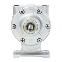
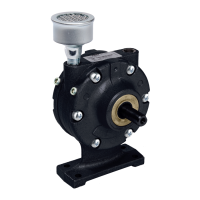
Worm Gear Reducer Series A-F
Gear Reducer Specifications
All output shafts are in the standard location.
Model Air Motor Ratio
AG803 4AM 20:1
AG805 4AM 40:1
AG807 4AM 60:1
AG809 6AM 10:1
AG811 6AM 20:1
AG816 8AM 20:1
Service, Parts, or Repair
For service, parts or repair of the worm gear reducer, contact the
manufacturer listed on the nameplate.
Part No. 45-200 D170PL (Rev. S)
TROUBLESHOOTING GUIDE
Problem
Reason and Remedy for Problem
Low Torque Low Speed Won’t Run Runs Hot
Runs Well
Then Slows
Down
• • •
Dirt or foreign material present. Inspect and ush.
• • •
Internal rust. Inspect and ush.
• •
Low air pressure. Increase pressure.
•
Air line too small. Install larger line(s).
• •
Restricted exhaust. Inspect and repair.
• • • •
Motor is jammed. Have motor serviced.
• •
Air source inadequate. Inspect and repair.
• •
Air source too far from motor. Recongure setup.
 Loading...