13
8. Coat the threads of eight 7/16-14 x 5-¾ inch long grade 8 cap screws with Loctite®
#242 or equal and insert through holes in the flange and thread into bottom opening of
suction tube extension. Torque cap screws and nuts to 40 ft-lb (54 N-m).
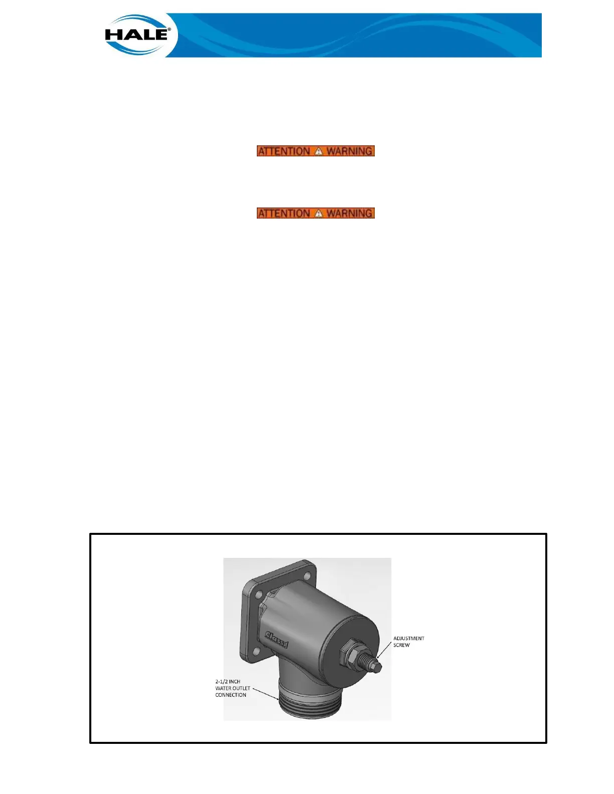
2.2.3 Plumbing Relief Valve
MALE THREADS ON RELIEF VALVE OUTLET ARE SHARP AND CAN CAUSE SEVERE
CUTS. BE CAREFUL WHEN WORKING AROUND THE EXPOSED THREADS ON THE RE-
LIEF VALVE OUTLET.
THE OUTLET OF THE RELIEF VALVE CAN FLOW LARGE VOLUMES OF WATER UNDER
PRESSURE. THEREFORE, THE DISCHARGE MUST BE PIPED IN A MANNER THAT WILL
NOT EXPOSE PERSONNEL TO HIGH PRESSURE WATER STREAMS.
NOTE
THE RELIEF VALVE IS ATTACHED TO THE HALE MIV WHEN SHIPPED FROM THE FAC-
TORY. APPARATUS CONFIGURATION MAY REQUIRE THAT THE RELIEF VALVE BE
MOUNTED IN A REMOTE LOCATION. STEP 1 BELOW PROVIDES PROCEDURES FOR
MOUNTING RELIEF VALVE IN A REMOTE LOCATION.
1. To Mount the relief valve in a remote location do the following:
a. Remove the four 7/16-14 UNC X 1-¼ inch long hex head cap screws that secure
the relief valve to the mounting pad on the Hale MIV body.
b. The relief valve mounting pad on the Hale MIV valve body has 2-½ inch NPT fe-
male threads, install a 2-½ inch NPT threaded pipe nipple into the mounting pad
or a use a Hale type 115 flange.
c. Install a 2-½ inch NPT Hale type 115 4-3/8 inch bolt circle flange onto the oppo-
site side of the pipe nipple.
d. Making sure the relief valve discharge is pointing down and away from the opera-
tor position, attach the relief valve adapter and relief valve to the Hale 115 flange
using a gasket, four 7/16-14 UNC X 2-½ inch long grade 8 zinc plated steel hex
head cap screws, Loctite® #242 and four 7/16-14 UNC zinc plated steel nuts.
Torque the cap screws and nuts to 40 lb- ft (54 N-m).
Figure 5. Relief Valve
 Loading...