MCP Process/Ismatec SA/15.11.2000/CB/
GP
33
Analog interface
Pin 9, speed OUT
The default setting is 0–10 V
DC
,
proportionally to the motor
speed 0–240.0 rpm.
Alternatively a frequency range
from 0–7.2 kHz is available.
Alternatives with sliding switch
S2 inside the pump (see page 34)
Pin 10, +5 V
DC
About +5 V
DC
are available.
(max. current 0.5 A)
Pin 13, speed intern
Depending on how the pump is
operated, pin 13 has different
functions:
Analog interface not activated
(Normal operation, i.e. pin 2 is
open) Pin 13 serves as auto-
start function.
If pin 13 is connected to pin 1
(GND), the pump can be started
and stopped directly from
the power supply (the power
switch must be on).
Analog interface activated
(Pin 2 on GND)
- Pin 13 open:
The rotation speed is adjusted
via pin 5 (speed IN).
- Pin 13 on GND:
The rotation speed can be
adjusted by the speed selector
on the control panel of the
pump.
Pin 14, output 1
Pin 15, output 2
Digital outputs in connection
with pin 7 (+26 V
DC
). Can only be
activated via RS232 interface;
e.g. with a software like the
ProgEdit.
Interface analogique
Pin 9, speed OUT
Le réglage d’usine par défaut est
0–10 V
DC
, proportionnel au
nombre de tours du moteur
0–240.0 t/min. Une zone de
fréquence de 0–7.2 kHz est à
disposition en alternative.
Possibilité de sélection au moyen
d’un interrupteur coulissant S2 à
l’intérieur de l’appareil (v.p. 34).
Pin 10, +5 V
DC
Environ +5 V
DC
sont à disposition
(courant maximal 0.5 A)
Pin 13, speed intern
Le pin 13 possède des fonctions
différentes en fonction du mode
d’opération:
Interface analogique non activée
(Mode d’opération normal,
c.-à-d. pin 2 ouvert) Le pin 13
a la fonction „auto-start“.
Si le pin 13 est connecté au pin 1
(GND), la pompe peut être mise
en route ou arrêtée directement
par l’alimentation électrique
(l’interrupteur principal doit être
sur ON).
Interface analogique activée
(Pin 2 sur GND)
- Pin 13 ouvert: La vitesse de
rotation doit être ajustée par le
pin 5 (speed IN).
- Pin 13 sur GND: La vitesse de
rotation peut être ajustée par le
sélecteur de vitesse sur le tableau
de commande de la pompe.
Pin 14, output 1
Pin 15, output 2
Sorties numériques en relation
avec le pin 7 (+26 V
DC
). Ne
peuvent être activées que par
l’interface RS232, p.e. avec le
logiciel ProgEdit.
Analogschnittstelle
Pin 9, speed OUT
Die werkseitige Einstellung ist
0–10 V
DC
, proportional zur
Motordrehzahl 0–240.0 min
–1
.
Alternativ steht ein Frequenz-
bereich von 0–7.2 kHz zur
Verfügung. Wahlmöglichkeit
mittels Schiebeschalter S2 im
Geräteinnern (siehe Seite 34)
Pin 10, +5 V
DC
Es stehen ca. +5 V
DC
zur
Verfügung. (max. Strom 0.5 A)
Pin 13, speed intern
Abhängig von der Betriebsart hat
Pin 13 unterschiedliche
Funktionen:
Analogschnittstelle nicht aktiviert
(Normalbetrieb, d.h. Pin 2 offen)
Hier dient Pin 13 als Autostart-
funktion. Ist Pin 13 mit Pin 1
(GND) verbunden, kann die
Pumpe direkt über die Netzspan-
nung gestartet bzw. angehalten
werden (Netzschalter muss
eingeschaltet sein).
Analogschnittstelle aktiviert
(Pin 2 auf GND)
- Pin 13 offen:
Die Drehzahl wird über Pin 5
(speed IN) vorgegeben.
- Pin 13 auf GND
Die Drehzahl kann am
Bedienungspanel der Pumpe
eingestellt werden.
Pin 14, output 1
Pin 15, output 2
Digitale Ausgänge in Verbindung
mit Pin 7 (+26 V
DC
). Können nur
über RS232-Schnittstelle aktiviert
werden; z.B. mit einer Software
wie ProgEdit.
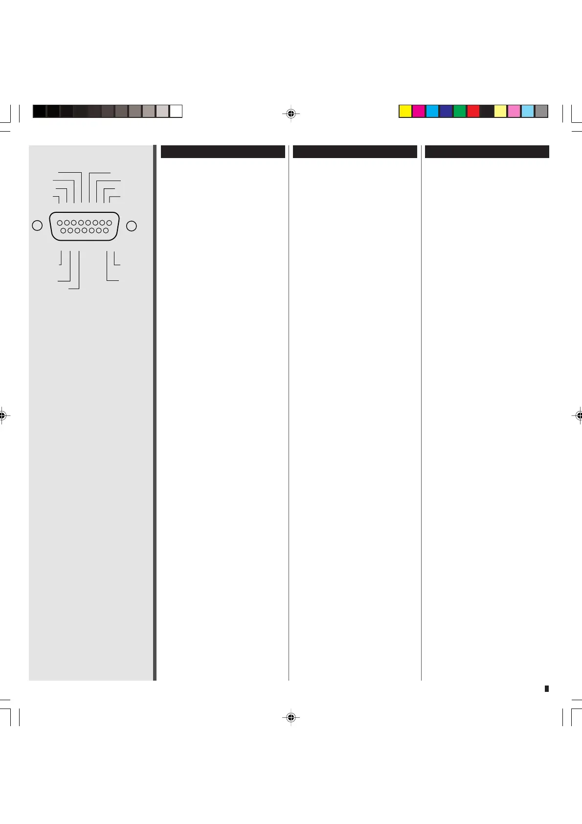
8 7 6 5 4 3 2 1
15 14 13 12 11 10 9
speed IN direction
input 1 start
+26VDC remote
input 2 GND
output 2 speed OUT
output 1 +5VDC
speed intern
Digitale Eingänge (TTL-Pegel)
Digital inputs (TTL-level)
Entrées numériques (niveau TTL)
Pin 2, remote
Pin 3, start
Pin 4, direction
Pin 6, input 1
Pin 8, input 2
Pin 13, speed intern
Analoge Eingänge
Analog inputs
Entrées analogiques
Pin 5, speed IN
0–5 V
DC
/ 0–10 V
DC
0–20 mA / 4–20 mA
Universal Ausgänge (PWM)
Universal outputs (PWM)
Sorties universelles (PWM)
Pin 14, output 1
Pin 15, output 2
Analog-Ausgang
Analog output
Sortie analogique
Pin 9, speed OUT
0-10 V
DC
/ 0-7.2 kHz