8
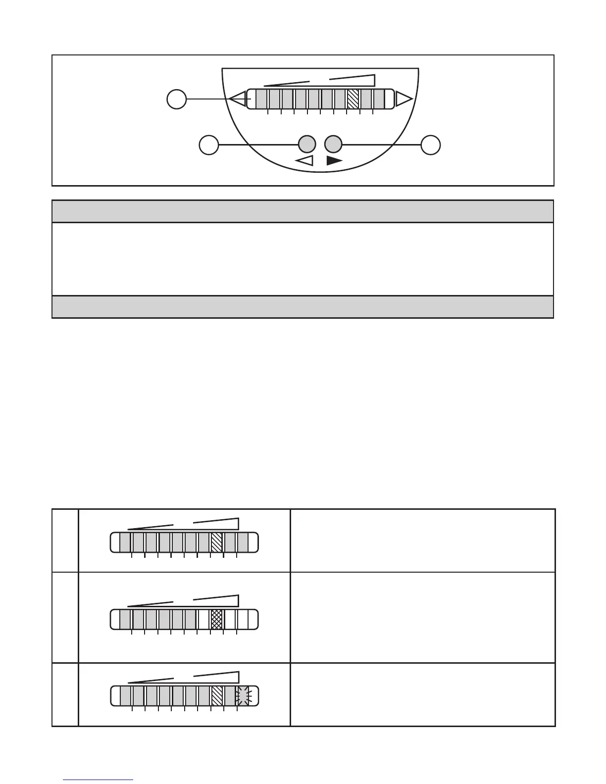
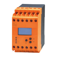
6 Operating and display elements
1: Operation display
•The green LEDs indicate the current flow (the LEDs 0 to 9 represent the range between
no flow and maximum flow)�
•A lighting LED indicates the position of the switch point (orange = output closed, red =
output open)�
2, 3: Setting buttons for adjustment and configuration
7 Set-up and settings for water
(Formediaotherthanwater→8.1:Lowflowadjustment).
► Switch on the supply voltage�
> All LEDs light and go out again step by step� During this time the output is
closed (if configured as normally open)� The unit is in the operating mode�
► Let the normal flow circulate in the installation�
► Check the display and determine further actions�
1
The factory setting is suitable for the applica-
tion�
► No further settings are required�
2
Your normal flow is below the representation
range of the display�
2 setting options:
► Changetheswitchpoint(→7.1).
► Carryouthighflowadjustment(→7.2).
3
Your normal flow exceeds the representation
range of the display (LED 9 flashes)�
► Carryouthighflowadjustment(→7.2).
Youcanrestorethefactorysettinganytime.(→8.3).