IO-Link Master with Modbus TCP Interface DataLine 4 Ports IP 65 / IP 66 / IP 67
>
9.3.5 Read input data of individual IO-Link ports
34466
Register area for separate access to input data of the individual IO-Link ports: →Single Port Access
(→ S. 98)
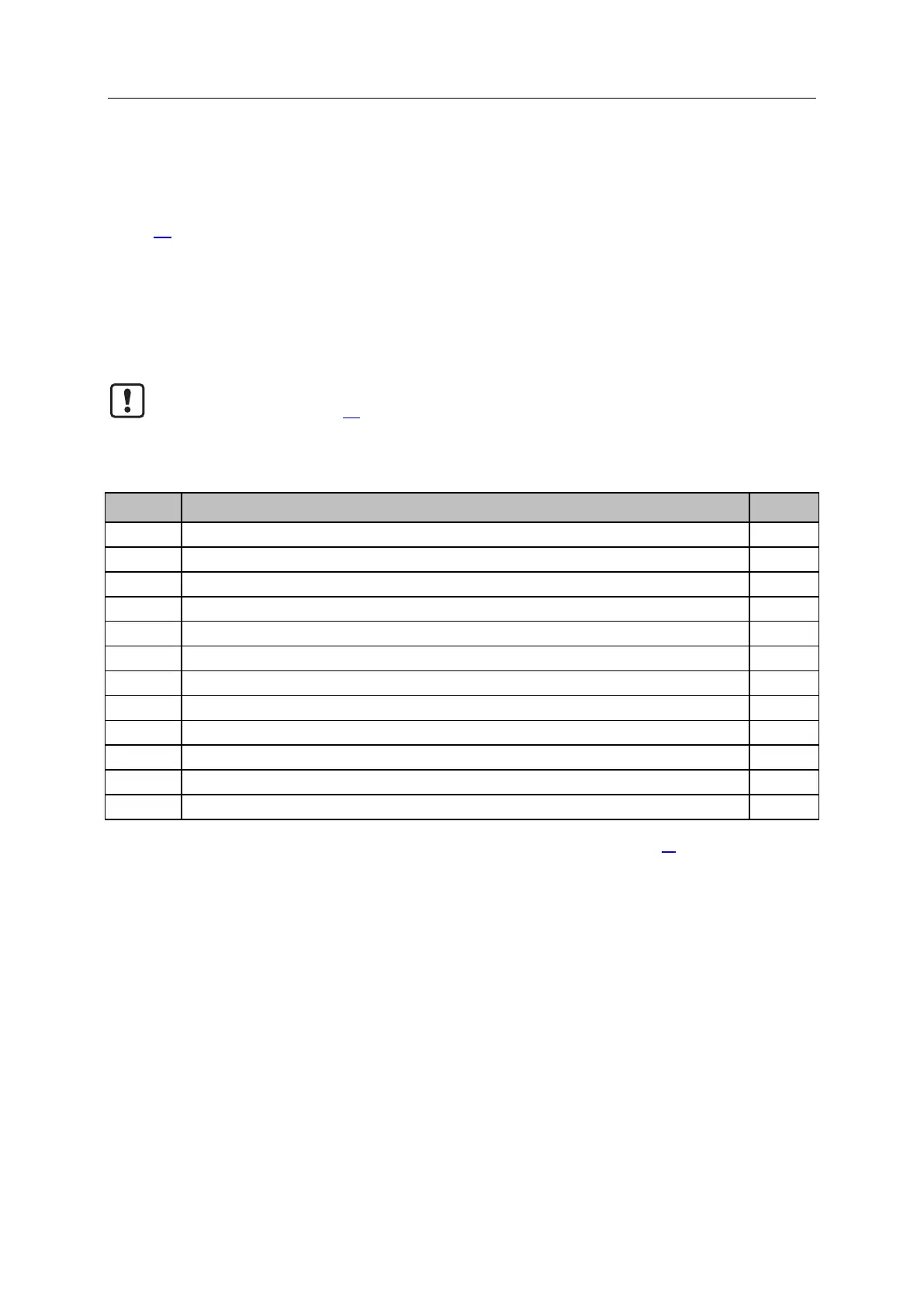
The area contains the following data for each IO-Link port X01...X04:
Digital input data at pin 2 / pin 4 (DI)
Status information of IO-Link port
Diagnostic and status information of the connected IO-Link devices
Input data IO-Link
Observe the general rules for access to the Modbus registers (→Rules for accessing the
Modbus registers (→ S. 73))!
The parameter "Invalid Data" indicates whether the read IO-Link input data is valid.
► Also read and evaluate the corresponding diagnostic information!
Port X01: Digital Input - Pin 2 / Pin 4 (DI)
Port X01: Diagnostic + Status Data
Port X01: Input Data - IO-Link (n bytes)
Port X02: Digital Input - Pin 2 / Pin 4 (DI)
Port X02: Diagnostic + Status Data
Port X02: Input Data - IO-Link (n bytes)
Port X03: Digital Input - Pin 2 / Pin 4 (DI)
Port X03: Diagnostic + Status Data
Port X03: Input Data - IO-Link (n bytes)
Port X04: Digital Input - Pin 2 / Pin 4 (DI)
Port X04: Diagnostic + Status Data
Port X04: Input Data - IO-Link (n bytes)
r ... read only
n = [2,4,8,16,32]; is determined by parameters [Process Data Length] (→Configuration Area (→ S. 88)
 Loading...