5. Adjustment
1. Set the selector switch (3) to liquid or gaseous media:
= liquid, = gas.
2. Apply the operating voltage. After the power-on delay time (approx. 30 s) has
elapsed the unit is ready for operation; (during this time flow may be indicated).
3. Set the preset flow and keep it constant. Turn the setting potentiometer (4) until
a green LED lights. The farther the green LED lit is away from the yellow LED, the
safer is the adjustment (excess gain for flow or temperature fluctuations).
6. Function diagram flow monitoring
Page 6
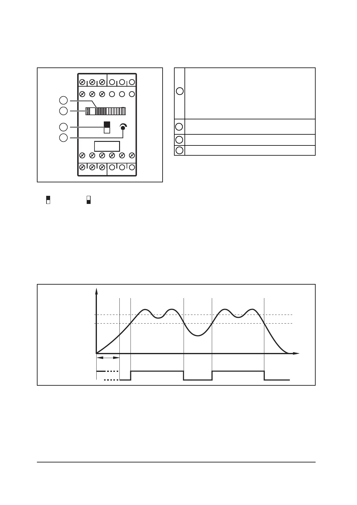
Row of LEDs
- red LED is lit: flow below the switch point
- yellow LED is lit: relay is energised,
flow has reached the switch point
- green LED is lit: flow above the switch point
Selector switch medium (liquid/gas)
LED red
- is lit in case of wire break or short circuit
Setting potentiometer for switch point
1
3
2
4