This document provides operating instructions for the DP2200 Analogue Threshold Display, a device designed for evaluating analogue signals.
Function Description
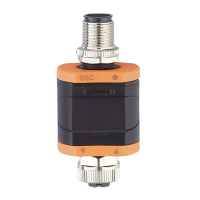
The DP2200 is used to evaluate an analogue signal (4-20 mA) from a connected sensor or another device with an analogue output (4-20 mA). It features one analogue current input and two outputs: output 1 (digital) and optionally output 2 (analogue current output). The device can operate in two primary modes: as a stand-alone device or as an IO-Link device.
In stand-alone mode, the device compares the measured current value with user-defined parameters and switches its output accordingly. The measured value is shown on an alphanumerical display, which can be scaled by the user through a 2-point scaling process. In this mode, IO-Link functionality is not active, but parameters can still be set using an IO-Link tool.
When operating as an IO-Link device, the DP2200 functions as an "analogue/IO-Link converter." The evaluation of the measured current value is dependent on parameters set via IO-Link tools or a PLC through IO-Link communication, or directly on the device. The IO-Link interface allows direct access to process and diagnostic data and enables parameter setting during operation. In IO-Link SIO mode, the device retains the stand-alone functionality, including displaying the measured value, and additionally converts the measured current for transmission via IO-Link to a PLC.
The current loop of the analogue input must be terminated, with only one load connected (either internal or external). The device is not suitable for environments with specific mechanical stability requirements (e.g., shock/vibration) and is intended for indoor use only.
Usage Features
The DP2200 offers a range of features for configuration and operation:
Parameter Setting:
Parameters can be set directly on the device via the menu or through an IO-Link tool. Access via an IO-Link tool takes precedence over menu-based parameter setting. IO-Link tools also support parameter cloning and backup. Some parameters are exclusively adjustable via the IO-Link interface. If scaling is applied, menu settings for switching thresholds (SP, rP, etc.) are also scaled, while via IO-Link, settings are displayed and executed in 0.01 mA steps (10-bit resolution).
Main Menu Parameters:
- SP1/rP1 (Set Point/Reset Point OUT1): Defines the upper/lower limits for measuring current at which OUT1 switches, including hysteresis. [rP1] is always lower than [SP1], and the device only accepts values meeting this condition. [rP1] automatically adjusts with changes to [SP1] to maintain the set hysteresis.
- FH1/FL1 (Min/Max Switching Limits for Window Function): Sets the upper/lower limits for current measurement within a window. These parameters are only displayed if the window function ([Fno] or [Fnc]) is selected for [ou1]. [FL1] is always smaller than [FH1] and adjusts with changes to [FH1] to maintain the set hysteresis.
- EF (Extended Functions): Accesses additional parameters.
Extended Functions Parameters (EF):
- rES (Restore Factory Setting): Resets all parameters to their factory defaults.
- A.Trm (Analogue Termination for OUT2): Configures OUT2 termination. [OFF] means OUT2 is externally connected, while [On] means OUT2 is internally terminated, and no external connection should be made for proper current measurement.
- ou1 (Output Function for OUT1): Selects the switching signal for current limits, including hysteresis functions (normally open [Hno], normally closed [Hnc]) and window functions (normally open [Fno], normally closed [Fnc]).
- dS1/dr1 (Switching Delay/Switch-off Delay for OUT1): Sets a delay time (0.0 to 50.0 s) for OUT1 switching, where 0.0 s means no delay.
- ScAL (Scaling of the Displayed Value): Acts as a multiplier for [C.ASP]/[C.AEP]. Options include [OFF] (no scaling), [cccc] (scaling without decimal place), [ccc.c] (1 decimal place), [cc.cc] (2 decimal places), and [c.ccc] (3 decimal places).
- C.ASP/C.AEP (Customer-Specific Analogue Start/End Point): Settings for scaled display values, visible only if [ScAL] is active. C.ASP values correspond to 4 mA, and C.AEP values correspond to 20 mA. If scaling is set, C.AEP must be adapted accordingly. All displayed current values are interpolated based on a 2-point approximation.
- coLr (Display Colours and Colour Changes): Assigns "red" and "green" display colours within the measuring range. Options include continuously red [rEd], continuously green [GrEn], red when OUT1 switches [r1ou], green when OUT1 switches [G1ou], red when the measured value is between [CFL] and [cFH] [r-cF], and green when the measured value is between [CFL] and [cFH] [G-cF].
- cFH/cFL (Upper/Lower Value for Colour Change): Sets the upper [cFH] and lower [CFL] limits for colour changes when [coLr] is set to [r-cF] or [G-cF].
- diS (Refresh Rate of the Displayed Measured Value): Configures the display refresh rate. Options include [OFF] (display deactivated), [d1] (50 ms), [d2] (200 ms), and [d3] (600 ms). [d1] provides optimal readability even with unsteady input values.
- Lo/Hi (Min/Max Measured Input Values): Displays the lowest [Lo] and highest [Hi] measured input values. Memory can be deleted by selecting [Hi] or [Lo], pressing and holding [▲] or [▼] until [----] is displayed, then briefly pressing [•].
- dAP (Damping): Applies damping to the measured analogue value (0.000 to 4.000 s, T value: 63%). A value of 0.000 means damping is not active. Damping affects the set point, IO-Link process data, and display.
- Reset [Hi] and [Lo] memory: Resets both minimum and maximum memory values.
IO-Link Adjustable Parameters:
- C.uni (Customer-Specific Unit): Allows setting a customer-specific unit with up to 4 characters.
- S.Loc (Software Locking): With [ON], the device is locked for local menu settings. Unlocking is only possible via IO-Link.
- Application-specific tag: A customer-specific application description, up to 32 characters long.
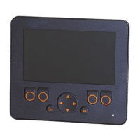
Operating and Display Elements:
The device features push rings (pushbuttons) for navigation: [esc] (Escape), [•] (Enter), [▼] (Down), and [▲] (Up). LEDs indicate output status (OUT1, OUT2 in yellow) and power status (green for OK, off for no voltage). The 7-segment LED display shows 4 digits and can change colour (red/green).
Locking/Unlocking:
The unit can be electronically locked to prevent unauthorized setting. To lock, press [esc] + [▲] simultaneously for 10 s until [Loc] is displayed. To unlock, repeat the process until [uLoc] is displayed. Customer locking ([C.Loc]) indicates active IO-Link communication (temporary locking), while software locking ([S.Loc]) means the sensor is permanently locked via software and can only be removed using IO-Link parameter setting software.
Timeout:
If no button is pressed for 30 s during parameter setting, the unit automatically returns to operating mode with unchanged values.
Numerical Entries:
Values can be changed continuously by holding down [▼] or [▲] for at least 2 s, or incrementally by pressing the button once.
Output Functions:
- Output 1 (pin 4): Digital output (SIO) or IO-Link interface. Selectable switching functions include hysteresis (normally open/closed) and window functions (normally open/closed). OUT1 changes status based on input signal relative to set switching limits.
- Output 2 (pin 2): Analogue output, looping through the analogue input signal.
Maintenance Features
The DP2200 is designed for maintenance-free operation.
- Only the manufacturer is authorized to repair the unit.
- After use, the device should be disposed of in an environmentally friendly manner according to national regulations.
- For cleaning, disconnect the unit from the voltage supply and clean it with a soft, chemically untreated, and dry micro-fibre cloth.