DP2200 Analogue threshold display
8
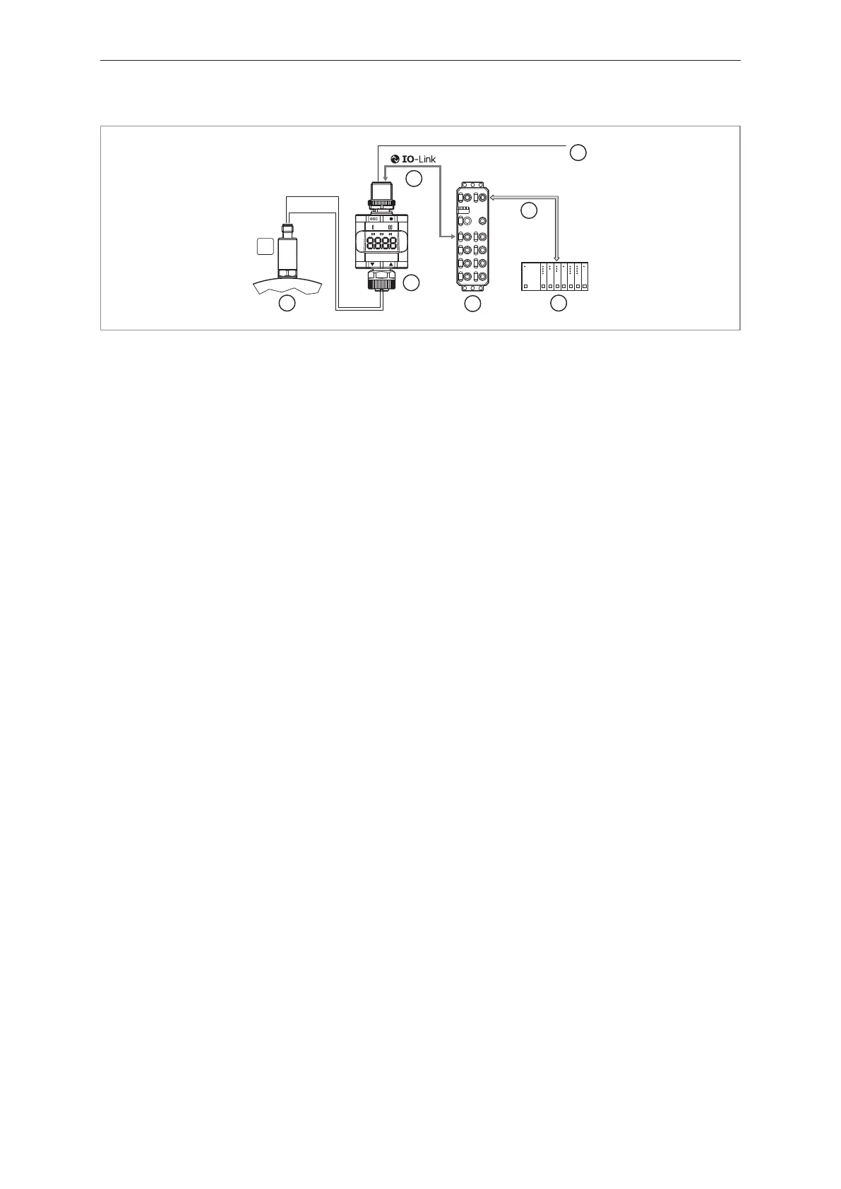
4.2.2 Application example
2
3
4
5
6
7
bar
4...20 mA
24 V DC
Fieldbus
4...20 mA
1
Fig.3: Application example with IO-Link master
1: Analogue sensor (e.g. pressure sensor) 2: Threshold display
3: Fully bidirectional IO-Link communication
• Remote display: reading and displaying the measured
current
• Remote parameter setting: reading and changing the
parameter setting
4: Looping through an analogue input signal
5: IO-Link master 6: Fieldbus (e.g. Profibus, Profinet etc.)
7: PLC
4.2.3 Functionality
In the IO-Link SIO mode, the device has the same functionality as a stand-alone device. The
measured value is also displayed.
Additionally, the device converts the measured current and transmits the value via IO-Link connection
to the PLC.
4.2.4 IO Device Description (IODD)
You will find the IODDs required for configuration of the IO-Link device as well as detailed information
about the process data structure, diagnostic information and parameter addresses at
documentation.ifm.com