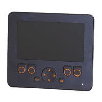
Analogue threshold display DP2200
11
u Tighten the cable plug using 1.8 ± 0.1Nm.
u Provide all outgoing cables with suitable strain relief after a maximum of 200mm. Observe the
minimum bending radius of the cables (Ò information from the cable manufacturer).
2-wire sensors can also be connected to the device.
u External interference suppression of inductive loads is required.
Always use the provided connection cables to connect other devices.
See also application examples (Ò Function)
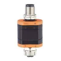
6.1 Removing the connector with vibration protection
u Press the connector against the unit and simultaneously loosen the coupling nut.
6.2 Cable length
• Without IO-Link communication: 30 m on each side
• With IO-Link communication: 20 m on the master side