Analogue threshold display DP2200
15
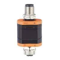
8.2 Menu structure
FH1 4.10...20.00
FL1 4.00...19.90
SP1 4.10...20.00
rP1 4.00...19.90
rESEF ---
A.trm On OFF
ou1 Hno Hnc Fno Fnc
dS1 0.0...50.0
dr1 0.0...50.0
ScAL OFF cccc ccc.c cc.cc c.ccc
C.ASP -746...9745
C.AEP -366...9366
coLr rEd GrEn r1ou G1ou r-cF G-cF
cFH 4.10...20.00
cFL 4.00...19.90
diS d1 d2 d3 OFF
Lo ---
Hi ---
dAP 0.000...4.000
1234
mA
3
1
2
1:
Operating mode: Operation (Ò/23)
2:
Main menu: Parameters of the main menu (Ò/15)
3:
Extended functions: Parameters of the extended functions (EF) (Ò/16)
Factory settings (Ò/26)
8.3 Parameters of the main menu
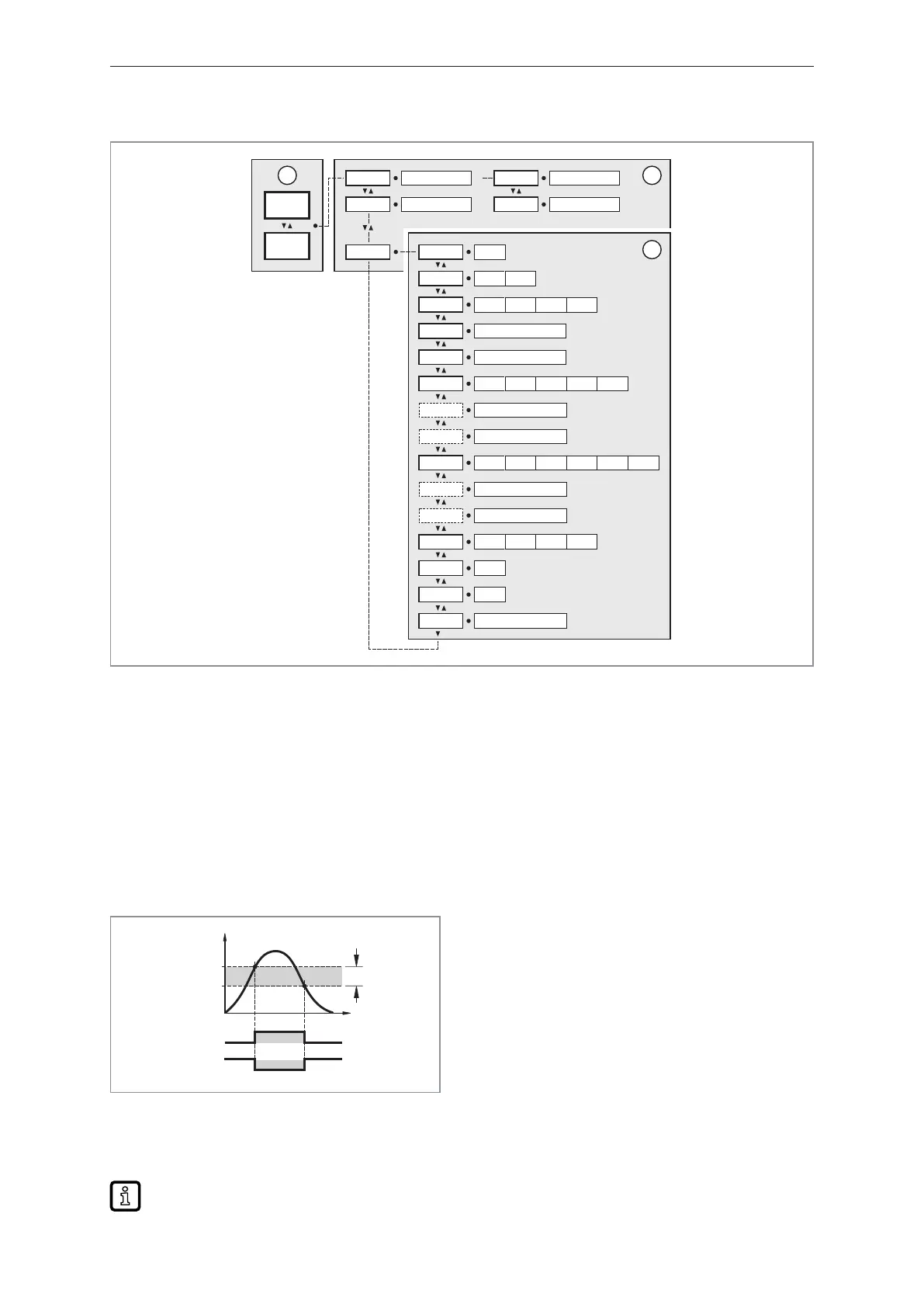
8.3.1 SP1/rP1 ─ set point/reset point OUT1
Upper/lower limit for measuring current at which OUT1 switches with hysteresis setting. Only
displayed if the hysteresis function [Hno] or [Hnc] is set in [ou1].
Hno
Hnc
HY
SP1
1
0
1
0
rP1
OUT1
I [mA]
t
Fig.7: Hysteresis functions
SP: Switch point
rP: Reset point
HY: Hysteresis
Hno: Hysteresis function normally open
Hnc: Hysteresis function normally closed
u Select [SP1] and set the value at which output OUT1 switches.
u Select [rP1] and set the value at which output OUT1 switches off.
[rP1] is always smaller than [SP1]. The device only accepts values which are lower than the
value for [SP1].