DP2200 Analogue threshold display
10
6 Electrical connection
The unit must be connected by a qualified electrician.
Observe the national and international regulations for the installation of electrical equipment.
Voltage supply according to SELV, PELV.
The circuit is insulated from device surfaces that could be touched with basic insulation according to
IEC 61010-1 (secondary circuit with max. 32 V DC, supplied from the mains circuit up to 300 V of
overvoltage category II).
The external wiring has to be carried out in a way that ensures the required separation from other
circuits.
CAUTION
Input current is not limited.
w No fire protection.
u Protect circuits.
Potential M12 connector
①
Fuse
L+ / supply voltage Pin 1 ≤ 2 A
Required tripping characteristic of the fuses:
T
fuse
≤ 120 s at max. 6.25 A (fire protection)
u Alternatively supply the device via a limited energy circuit according to IEC61010-1 or class 2
according to UL1310.
u Disconnect power.
u Connect the unit as follows:
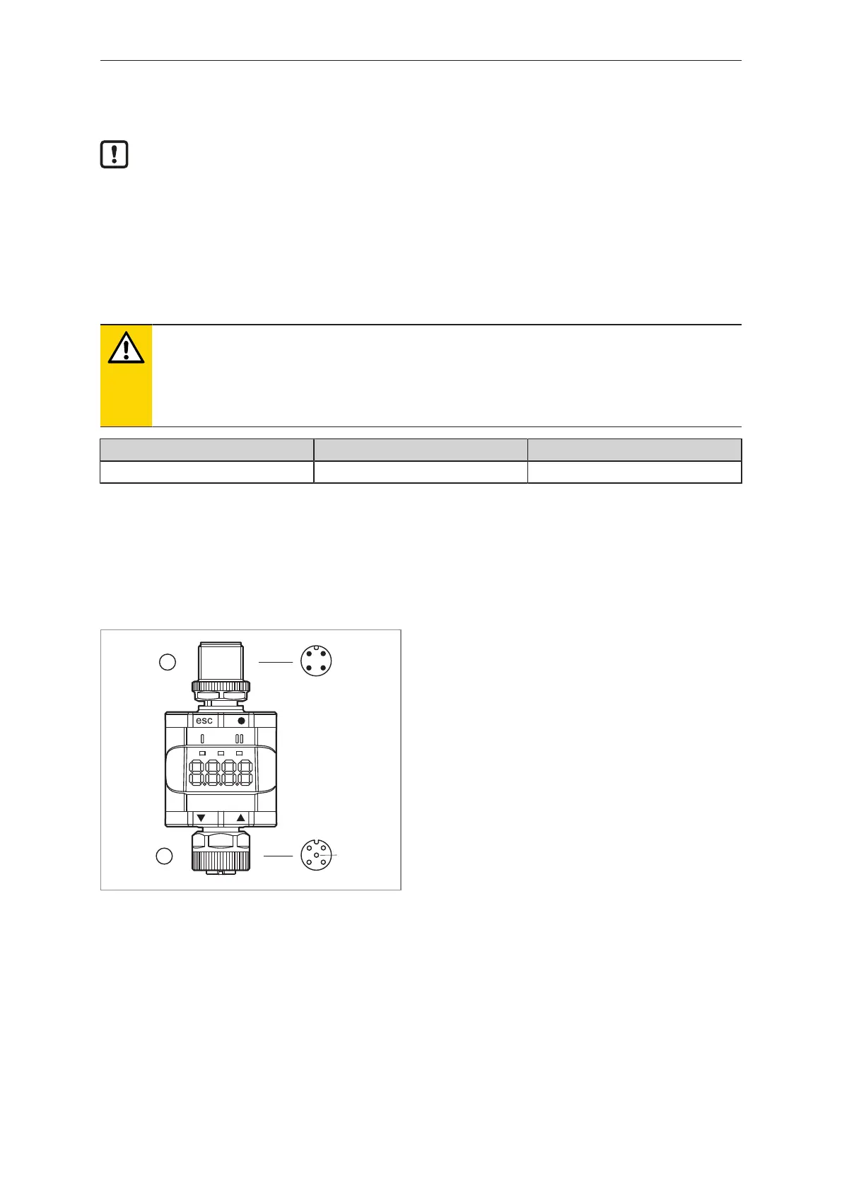
Fig.6: Electrical connection
1: 4-pole M12 connector
(Output side)
• Pin 1: L+ / supply voltage
• Pin 2: OUT2 (analogue output)
• Pin 3: L- / supply voltage
• Pin 4: OUT1 (digital output SIO / IO-Link)
2: 5-pole M12 female connector
(Input side)
• Pin 1: L+ / sensor supply
• Pin 2: Analogue input (4...20 mA)
• Pin 3: L- / sensor supply
• Pin 4: Not used
• Pin 5: Not used
The threaded connections in the device correspond to the M12 standard. To ensure compliance with
the specified protection rating, only cables that comply with this standard may be used. In the case of
self-assembled cables, the system manufacturer is responsible for the protection rating.
u Use connectors with gold-plated contacts.
u During installation, place the connectors vertically so that the coupling nut will not damage the
thread.
u Observe the coding of the connectors during installation.
u Tighten the cable sockets according to the torque specifications indicated by the cable
manufacturer. Maximum permissible tightening torque: 1.3 ± 0.1Nm