IHP: RC-S-TOUCH
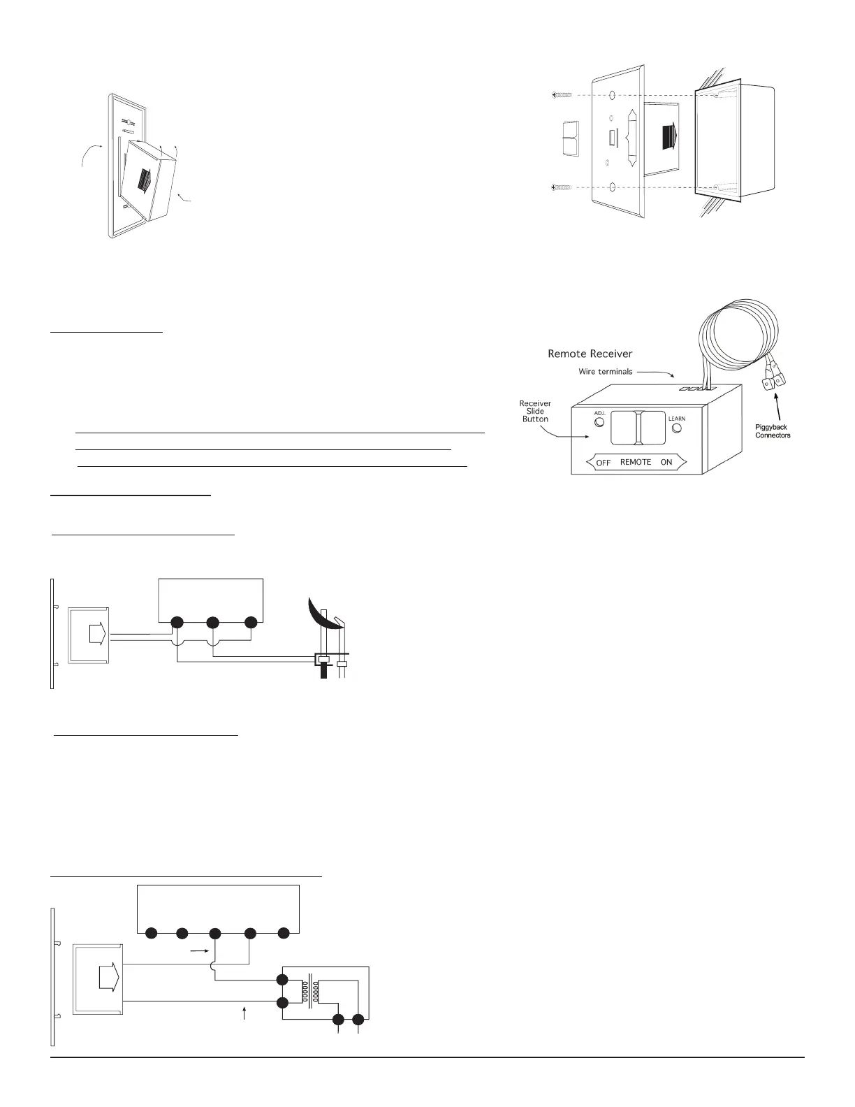
Position the receiver as shown in diagram
to the left with lower tab on cover plate
inserted into groove of receiver (Make sure
LEARN hole on cover plate properly aligns
with remote receiver). Pull receiver up and
snap into top tab of cover plate.
Position the cover plate so the word ON is
facing up; then, install the remote receiver
into the plastic switch-box using the two
long screws provided. Push the white
button over the receiver slide switch.
Remote Receiver
Cover Plate
(Rear View)
To attach Cover Plate to Receiver Box:
R
E
M
O
T
E
ON
OFF
LEARN
ADJ
.
W
ALL
Plastic Switch Box
Cover Plate
Receiver
Slide
Button
HEARTH MOUNT
The remote receiver can be placed on the replace hearth or under •
the replace behind the control access panel.
Use the wires attached to the remote receiver to connect to the gas •
valve or the electric module (piggyback connectors have both male &
female terminals for exibility).
Be sure that the connectors do not touch each other or other bare •
metal surfaces; this will cause the appliance to turn ON. The
connectors may be wrapped with electrical tape to prevent this.
FIG. #9
FIG. #11
FIG. #10
REV. 3-18-14 Page 4
WIRING INSTRUCTIONS
A qualied electrician should install the remote control system.
TERMINAL BLOCK
ON MILLIVOLT
GAS VALVES
TH
TP
TP
TH
THERMOPILE/
PILOT LIGHT
REMOTE
RECEIVER
Connect one wire from the remote receiver to the TH terminal on the •
gas valve.
Connect the other wire from the remote receiver to the TH/TP •
terminal on the gas valve.
WIRING MILLIVOLT VALVES
MILLIVOLT SYSTEM CHECK
Ensure that the pilot ame is lit.•
Slide the 3-position button on the remote receiver to the • ON position. The main gas ame (i.e., the re)
should ignite.
Slide the button to • OFF. The main ame should extinguish (the pilot ame will remain ON).
Slide the button to • REMOTE, then press the ON button on the transmitter to change the system to ON. The main
gas ame should ignite.
WIRING ELECTRONIC SPARK IGNITIONS
ELECTRONIC MODULE
TR
TH
REMOTE
RECEIVER
neutral wire
24VAC
hot wire
120VAC
110/24VAC
Transformer
The remote control receiver can be connected, in series, to
a 24VAC transformer to the TR (transformer) terminal on the
ELECTRONIC MODULE. Connect the hot wire from the 24VAC
transformer to either of the wire terminals on the remote
receiver. Connect another wire between the other receiver wire
terminal and the TH (thermostat) terminal on the ELECTRONIC
MODULE.
FIG. #12
FIG. 13
P/N 900259-00 Rev. A
 Loading...