20
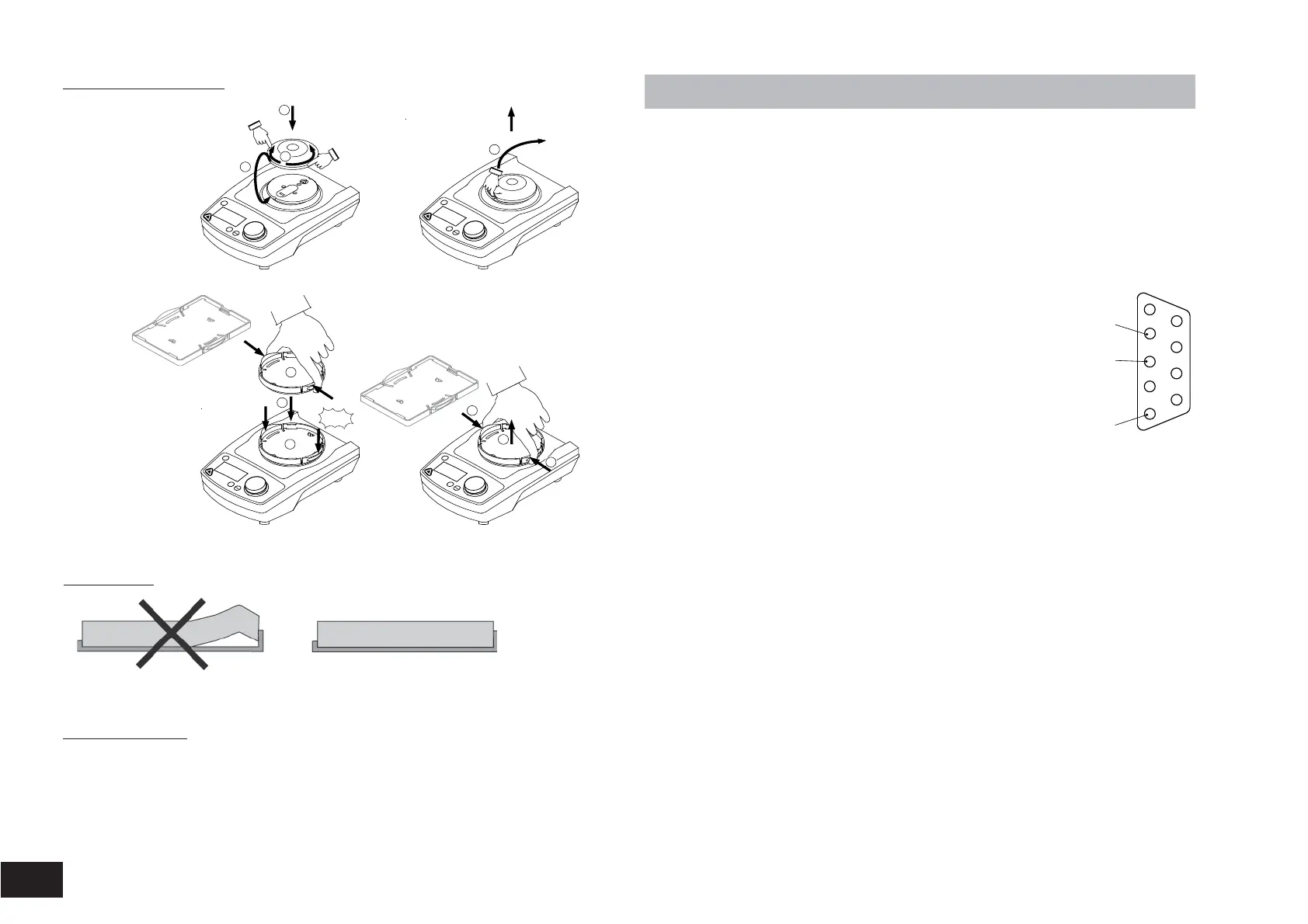
Changing attachments
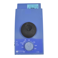
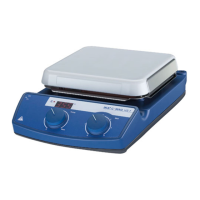
MS 3.1
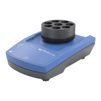
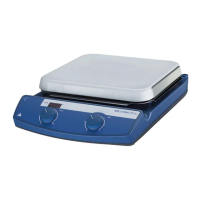
MS 3.3
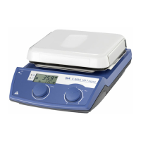
MS 3.4
Using inserts
1
2
3
1
2
3
1
2
1
"click"
1
!
Start
Stop
Power
Set
Time
!
Start
Stop
Power
Set
Time
!
Start
Stop
Power
Set
Time
!
Start
Stop
Power
Set
Time
Lorem ipsum
Other accessories
• PC 1.2
• PC 2.1
• labworldsoft
®
, from version 5.0 on
• Adapter
• Analog cable
• Software
Interface and output
The device is equipped with a 9-pin SUB-D connector on the rear side of the
device.
Serial interface RS 232 C
The serial assignment of the socket can be used to control the device exter-
nally by means of a PC and a suitable application program, e.g. labworld-
soft
®
, from Version 5.0 on.
Configuration of the serial interface RS 232 C
• The function of the interface line between the laboratory
device and the automation system is a selection of the
signals specified in EIA S
tandard RS 232 C, corr
esponding
to DIN 66020 P
art 1. F
or the assignment of the signals,
please r
efer to the illustration.
• S
tandard RS 232 C applies to the elctronic pr
oerties of
the interfaces and the assignment of signal states inac-
cor
dance with DIN 66259 Part1.
•
Transmission procedure: Asynchronous character transmission in start-stop mode
• Type of transmission: full duplex
•
Character format: Character creation according to the data format in DIN
66022 for start-stop mode. 1start bit; 7 character bits; 1parity bit (even); 1 stopbit.
• Transmission speed: 9600 Bit/s
• Data flow conr
ol: no
Instruction Syntax
Here applies the following:
• The instructions ar
e generally sent from the pr
ocessor (master) to the
laboratory instrument (slave).
•The labor
atory instrument exclusively sends on demand of the processor
.
Even err
or codes cannot be spontaneously communicated from the labora-
tory instrument to the processor (automatic system).
• Instructions and par
ameters as well as subsequent parameters are separat-
ed by at least one blank. (Code: hex 0x20)
• Each individual instruction including parameters and data as well as each
r
eply ar
e terminated with CR LF (Code: hex 0x0D and 0x0A) and have a
maximum lenght of 80 char
acters.
• The decimal separator in a floating point number is the point (Code: hex
0x2E).
1
5
RxD
TxD
GND