9850-000910-00. E&OE.
Incoming Supply
120 - 277VAC
Mains supply protection:
Provided by installer (6A Type C MCB recommended)
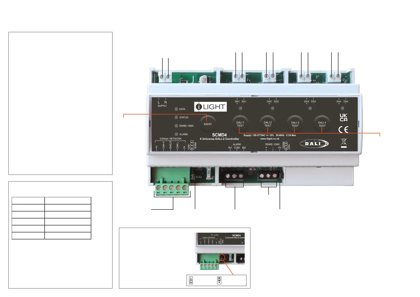
Status LED
Green LED ashes – device OK
Data LED
Red LED ashes when messages sent on network
Alarm LED
Red LED solid on for local initiated alarm
Red LED ashes for network initiated alarm
RS485 / DMX LED
Green LED ashes when DMX or RS485 messages are sent or
received
Device Identication
Press and release switch.
Sending a message to identify the device on the network
(red Data LED ashes).
DALI LEDs
Yellow LED ashes when messages sent on DALI bus
Yellow LED solid on - short circuit on DALI bus
DALI Universe Test Buttons
10 second press to enter Test mode
Sequential presses Broadcast all on all off
10 second press to exit Test mode.
Device LEDs and Buttons
Typical Connection Diagram
SCMD4
4 Universe Addressable DALI-2 Controller
NL
RS485 / DMX
termination
RS485 / DMX
Connection
Auxiliary Volt Free Contacts
2 x Volt free inputs
iCAN Network
Termination
Connection to the
iCAN Network
Device
Identication
Switch
DALI Output
Universe 1
DALI Output
Universe 2
DALI Output
Universe 3
DALI Output
Universe 4
DALI Universe
test buttons
Function iCANnet Cable Colours
0V Black
CAN L Blue
Shield Silver
CAN H White
+VDC Red
Maximum segment distance: 500m (1640 ft)
Devices per segment: 100 (without bridge or repeater)
Consult iLight for information on alternative cable types.
IMPORTANT NOTE: Connecting a mains potential cable to the
iCAN Network terminals is likley to damage the unit and other
devices connected, and invalidate warranty.
iCAN Network Connections
iCANnet Network termination
SCMD4 is supplied with termination
disabled as standard. If it is connected
as an end device on the iCAN network,
the jumper will need to be moved to
enable termination.
To enable termination, move the jumper
outwards from the inner two pins to the
outer two pins.
Termination
OFF
Termination
ON
 Loading...