9850-000779-01
. E&OE.
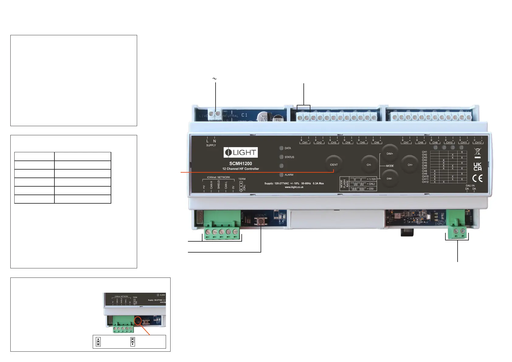
Status LED
Green LED ashes – device OK
Data LED
Red LED ashes when messages sent on network.
Alarm LED
Red LED ashes for network initiated alarm
Device Identication
Press and release switch.
Sending a message to identify the device on the network
(red Data LED ashes).
Device LEDs and Buttons
Typical Connection Diagram
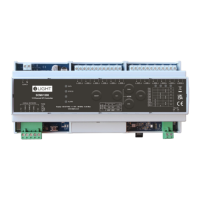
SCMH1200
12 Channel DINrail Mount HF Controller
DALI Input
Incoming Supply
100 - 230V 0.1A - 0.2A
iLight Network
Termination
Connection to the
iLight Network
Device
Identication
Switch
Output channels.
1-10V / DSI / DALI
Function iCANnet Cable Colours
0V Black
CAN L Blue
Shield Silver
CAN H White
+VDC Red
Maximum segment distance: 500m (1640 ft)
Devices per segment: 100 (without bridge or repeater)
Consult iLight for information on alternative cable types.
iCAN Network Connections
Network Power Requirements
Nominal operating voltage: 15V (12-18V)
IMPORTANT NOTE: Connecting a mains potential cable to the
iCAN Network terminals is likley to damage the unit and other
devices connected, and invalidate warranty.
Network termination
SCMH1200 is supplied with termination
disabled as standard. If it is connected
as an end device on the iCAN network,
the jumper will need to be moved to
enable termination.
To enable termination, move the jumper
outwards from the inner two pins to the
outer two pins.
Termination
OFF
Termination
ON
 Loading...