9
Electrical connection
Before installing the appliance ensure that the existing electrical systems comply with the law and correspond
to the data on the appliance label to be installed in terms of voltage [V], frequency [Hz] and input power [W].
The appliance has a power cable with a 16A Schuko plug.
Once the installation is complete the plug must be accessible. If this is not pos-
sible, the power supply system must be equipped with a disconnector.
Do not wind up the power cable and make sure it is does not hinder or endanger
people passing through the area.
Make sure the power cable is not crumpled, squashed or bent.
The power cable must not get wet , come into contact with sharp or hot objects,
or be exposed to corrosive substances.
Avoid contact between the power cable and children or animals.
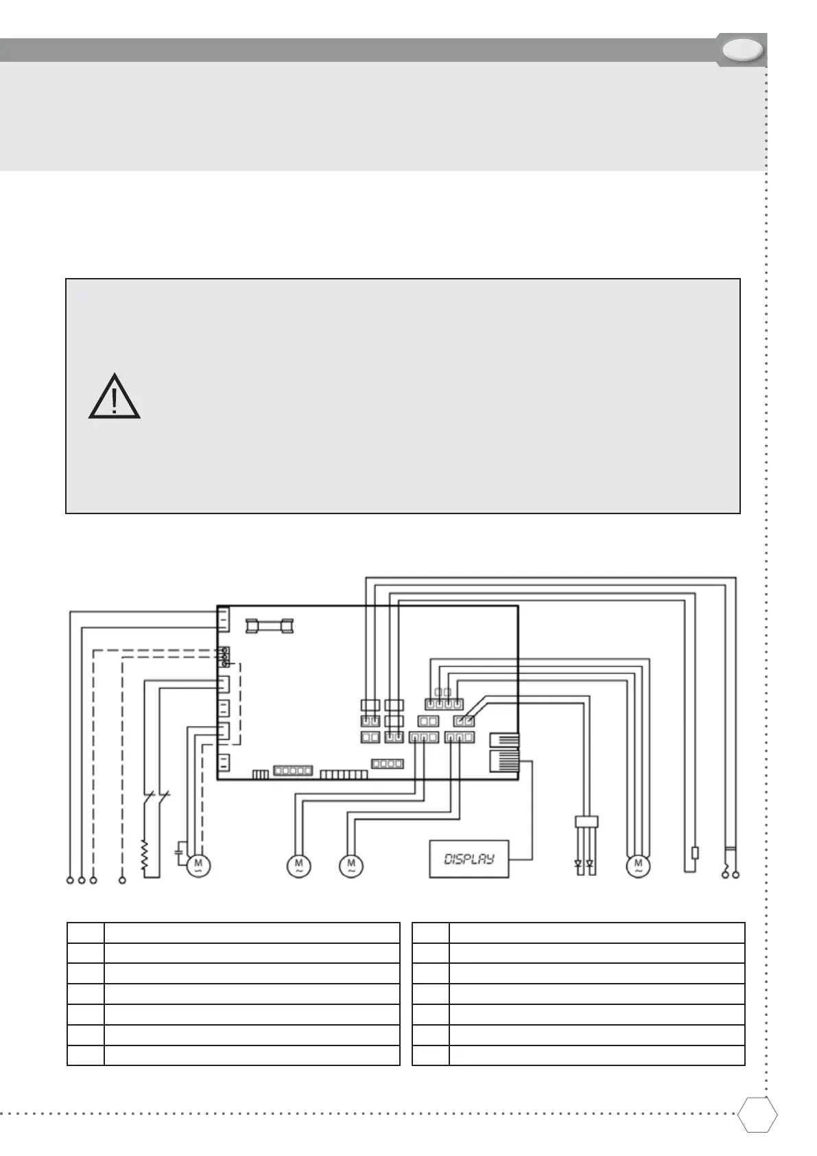
Wiring diagram
1
2
7
3 4 5 6 8 9 10 11 12 13 14
1 Power board
2 Fuse
3 Plug (IEC)
4 Earth
5 Heating element
6 Compressor
7 Thermal cut-off
8 Left condenser fan motor
9 Right condenser fan motor
10 Display
11 LED
12 Evaporator fan motor
13 Air probe
14 Core probe
INSTALLATION