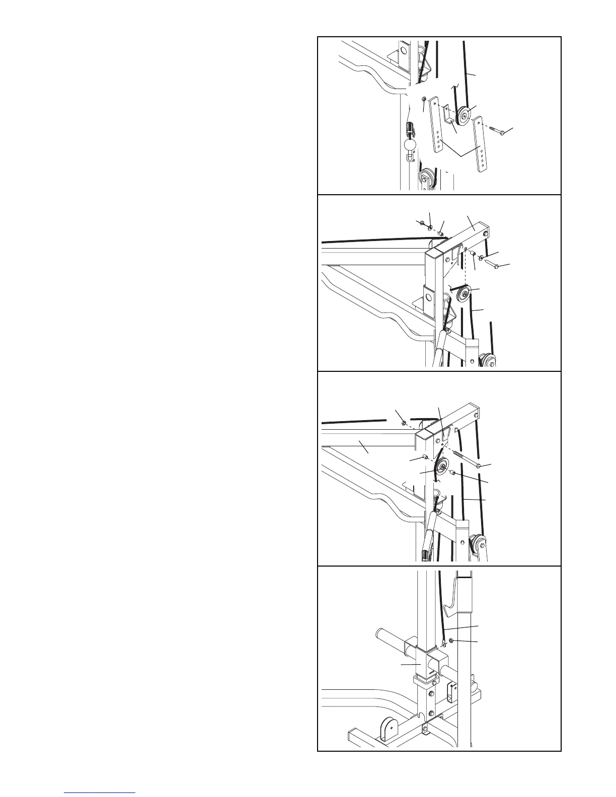
32. Wrap the Carriage Cable (60) around an 88mm
Pulley (36). Attach the Pulley inside the Top
Frame (9) with an M10 x 75mm Bolt (73), two
17mm Spacers (96), two M10 Washers (79), and
an M10 Nylon Locknut (77).
32
33. Wrap the Carriage Cable (60) around an 88mm
Pulley (36). Attach the Pulley between the Right
and Left Frames (5, 6) with an M10 x 81mm Bolt
(65), two 15mm Spacers (83), and an M10 Nylon
Locknut (77).
34. Attach the end of the Carriage Cable (60) to the
welded bolt on the Weight Carriage (25) with an
M10 Nylon Locknut (77).
33
34
14
77
79
79
77
5
6
73
65
9
96
60
60
77
25
96
83
83
36
31
31. Wrap the Carriage Cable (60) around a 4 1/2”
Pulley (35). Attach the Pulley and a Large Cable
Trap (55) to the single set of holes in the pair of
Pulley Plates (31) with an M10 x 45mm Bolt (76)
and an M10 Nylon Locknut (77).
60
35
77
76
31
55
60
36