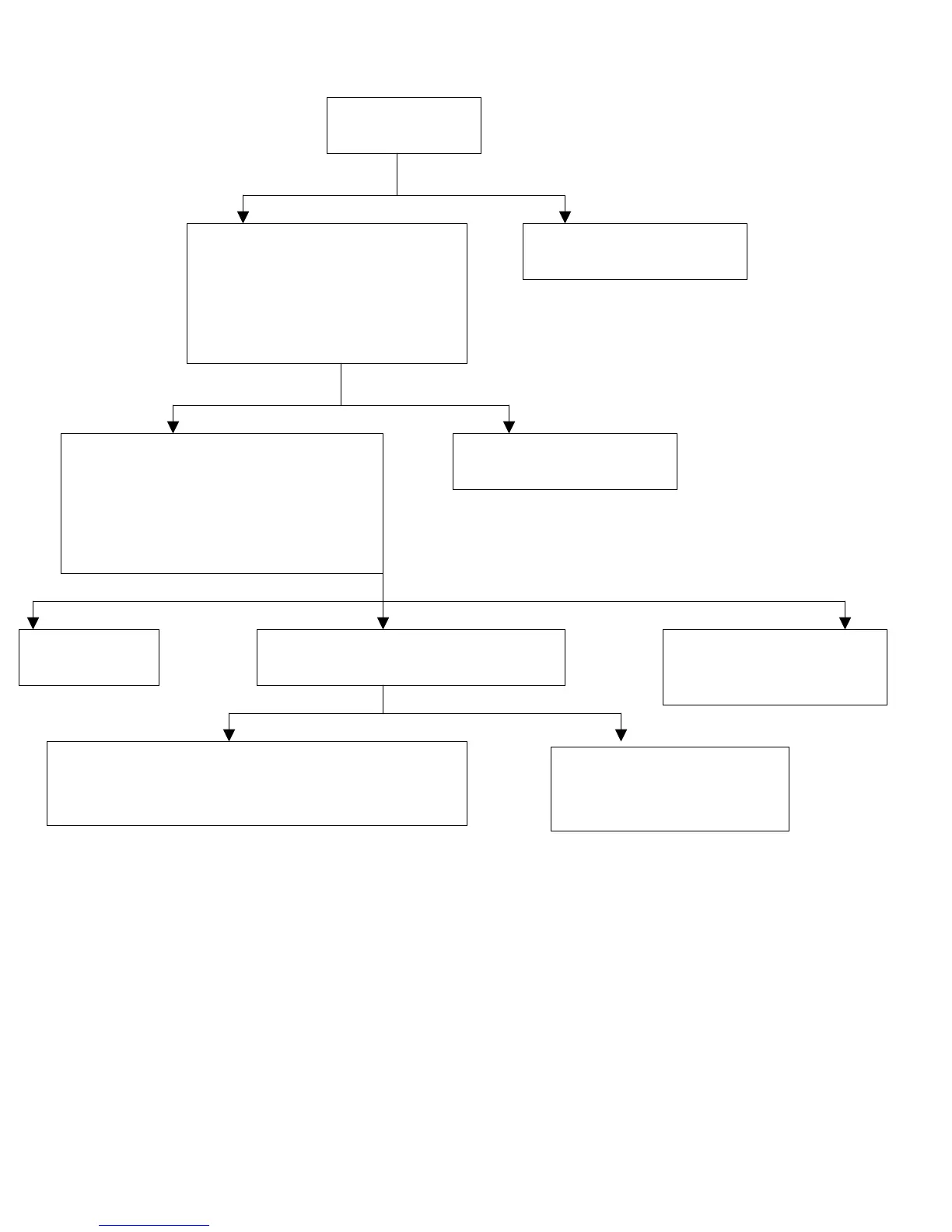
g) E010:
Wiring Good Wiring Bed
3
J6 Covers One Pin J6 Covers both Pins
Fix connection according
to the instruction.
Remove it and place it so
it covers only the left pin.
Make sure the J6 on the control
box is open, i.e.: it doesn’t cover
both pins (cover only the left
one). J6 is located on the left
edge of the PC Board when
facin
the Power switch.
Check if wiring
is accurate
Check that the voltage between 10 &
16 on the bar closest to the Power
switch is 115V during an exposure and
that the resistance is between 1.2-1.6Ω
(Shut down the machine before
checkin
the resistance
Voltage & Resistance Good Voltage Good-Resistance Bad No Voltage
Resistance Good Resistance Bad
Machine
should work
Replace PC Board
P/N: 897-ZZ1145021 (115V).
P/N: 897-ZZ1145051 (230V)
Check the resistance of the tube head
Should be between 1.2-1.6
Replace the Arm
P/N: 9992700105 (Folding Arm)
P/N: 9992700108 (Standard Extension Arm (35.4”))
Replace the Tube
P/N: 9992700130 (115V)
P/N: 9992700330 (230V)