1903KITINE18_02 (E100901B_ENG) 01/02/2016
4
6) Using a more or less 2mt long 4G1.5
cable connect the motor supply
contacts (passing through the cable
holder) with the magneto thermal relay
contact T1, T2 e T3.
To connect the motor use a Y
connection (supply is 3x400V); ground
must be connected with the whole
ground system.
7) Using a 0.5 mm
2
cable make the
following control electric connection.
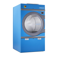
a) Neutral connection (blue cable):
make a bridge between contacts:
A1 (VE), A2 (SX), A1 (DX).
b) From contact A2 (DX) with
insulated fork plug to contact 22
(SX) with insulated fork plug
c) From contact 21 (SX) with male
pin, to the connector (drawing I,
ref. 22). On the connector (position
7) it is already present the female
pin which arrives from contact JP9-
5 of the electronic board and which
control right rotation.
d) With insulated fork plug from
contact A1 (SX) to contact 21 (DX)
with insulated fork plug.
e) With insulated fork plug from
contact 22 (DX) to the connector
poisoned on the below side of the
electric board. On the connector
(position 7) it is already present the
female pin which arrives from
contact JP9-5 of the electronic
board and which control left
rotation.
f) Take of the cable from the
contactor 95 of the fan thermal
relay and connect it to the thermal
relay near the DX contactor.
g) Make a bridge between the contact
96 and the thermal relay next to
VE and the contact 95 of the
thermal relay next to DX contactor.
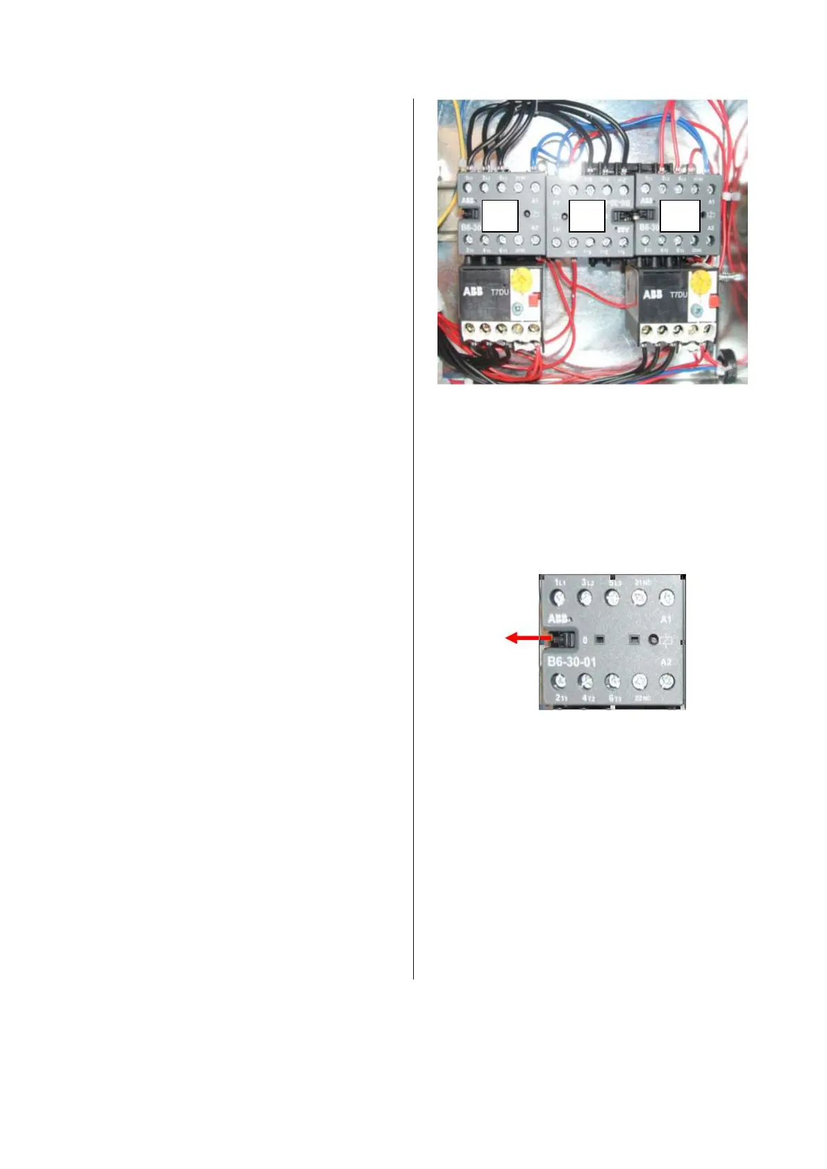
7. WORKING TEST
Each single contactor can be manually
tested. Using a screwdriver pull the
apposite pin until the contacts are closed.
Check the right rotations sense and, in
case, change the position of the two
phases coming out form the contactor.
 Loading...