1903KITINE18_02 (E100901B_ENG) 01/02/2016
3
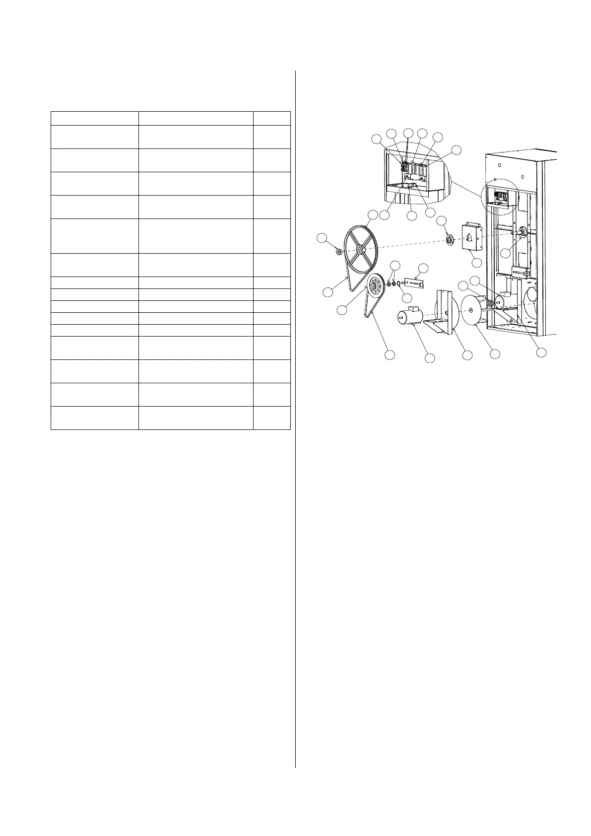
4. KIT COMPOSITION
The kit is made of the following parts:
RELE TERMICO T16
1,7A – 2,3A, 1NC+1NA
MOTORE 0,37KW - 4P
- 230/400V - 50Hz
PULEGGIA SPA 67x1
FORO 14 - CAVA 5
SUPPORTO MOTORE
INVERSIONE ES10/34
VERNICIATO
BARRETTE COL.
INVER. BSM6-30
5. MECHANICAL INSTALLATION
Check the exploded view on the right:
a) Unscrew the snub pulley support
(position 8).
b) Unscrew the regulation screw of the
snub pulley support (position 8)
c) Take off the transmission belt
(position 5) which connects the fan
motor (position 26) with the snub
pulley (position 6)
d) Mount the pulley (position 4) on the
motor tree (position 3) and close it
with the apposite dowel.
e) Mount the motor support (position 25)
on the dryer chassis.
f) Fix the motor (position 3) on its
support (position 25).
g) Use the belt (position 5) to connect
the reversing motor pulley (position 3)
to the snub pulley (position 6).
h) Screw the support regulation screw
until the belt is tensioned (position 5)
i) Close the fixing screw of the double
pulley.
6. ELECTRIC INSTALLATION
1) Fix the two B6 contactors on the
omega bar, which is positioned on the
right of the actual fan contactor (which
will be indicated as VE).
2) Mount the two black bridge on the SX
and DX contactor. Check that the
contact position printed on the bridge
are respected.: 1-L1 to 1-L1 (DX); 3-
L2 to 3-L2 (DX); 5-L3 to 5-L3 (DX); 2-
T1 to 2-T1 (DX); 4-T2 to 4-T2 (DX); 6-
T3 to 6-T3 (DX);
3) Fix the thermal relay on the right
contactor (which will be indicated with
DX), inserting the contacts T1, T2 and
T3.
4) Fix the thermal relay at 2,4 A.
5) Using a 1.5 mm
2
cable, make the
following power terminal electric
bridge between the VE fan contactor
and the SX contactor.
a) L1 (VE) – T3 (SX)
b) L2 (VE) – T2 (SX)
c) L3 (VE) – T1 (SX)
1
2
26
4
5
6
7
8
9
10
11
12
13
14
25
3
24
15
16
17
18
21
22
23
19
20
 Loading...