8
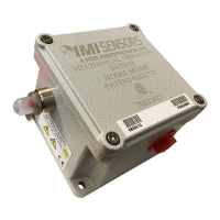
Gap Setting
The factory setting is determined by a 1/4" gap measurement illustrated in
Figure 4. Adjust the sensitivity screw clockwise or counter-clockwise to achieve
the dimension shown.
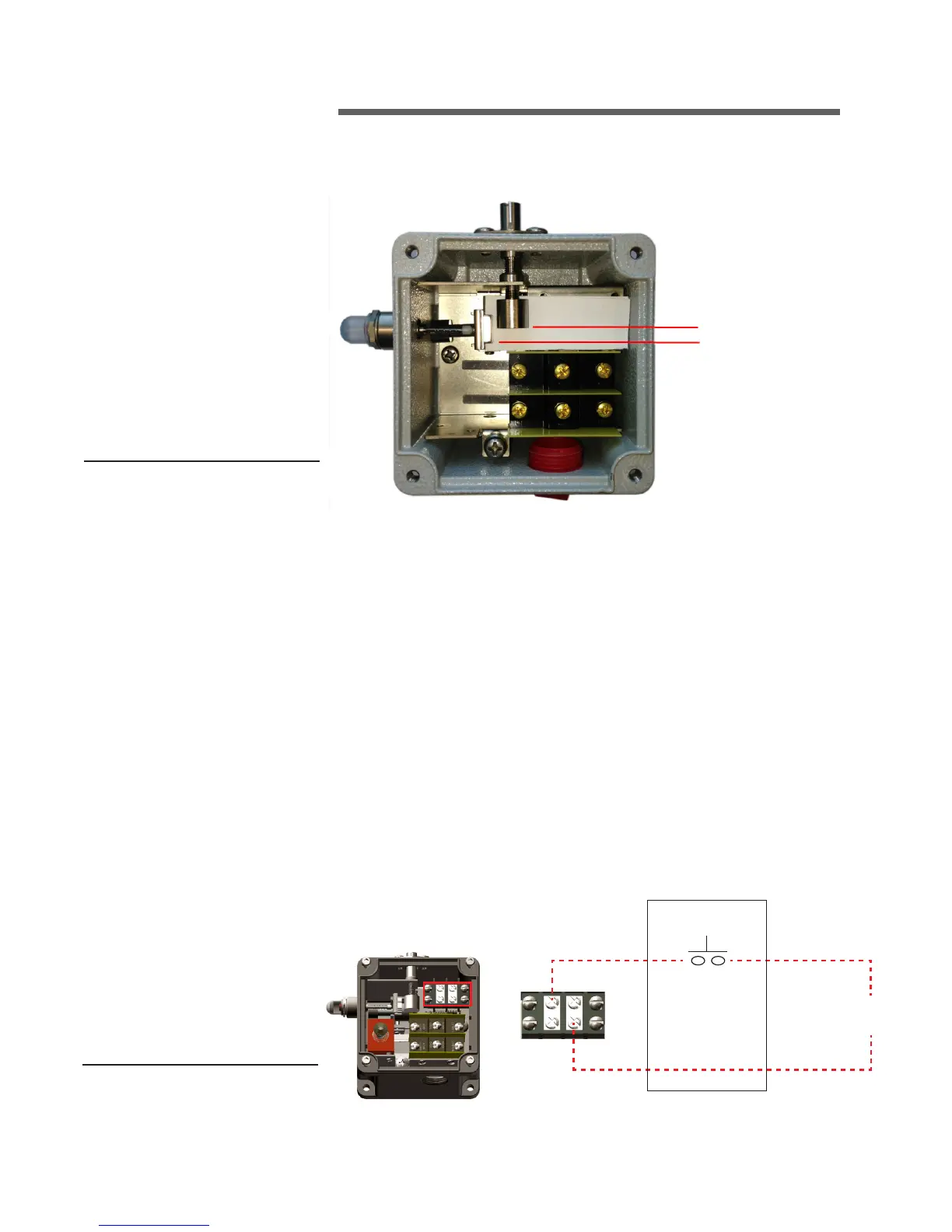
Switches with Remote Reset Option
A switch with the remote reset option uses an internal electrical solenoid with
a plunger to remotely reset the internal trip mechanism. The solenoid requires
electrical power to operate and is typically provided from the starter equipment
in conjunction with a remote reset push-button station.
A mechanical switch is designed to sense a high shock or severe vibration
event and cannot sense low vibration frequencies sometimes associated with
cooling towers. When the switch trips it typically means a catastrophic event
may have occurred. Upon a trip event, a thorough inspection of the tower, fan
and drive train should be performed before restarting the fan motor. The opera-
tor should not simply reset the switch without an inspection being performed.
Figure 4
1/4" GAP
operation
Power Supply Source for
Remote Reset Circuit
Momentary Pushbutton
Operator Station
Note: Add trip delay
timer circuit if
required for hard
starting equipment
Operator staton provided by others
Figure 5
 Loading...